Electric Shaver USB C Mod (Phillip Norelco PQ208)
We calculate the final price from your selected file. You review and accept it before payment.
Saved on this device.

Modification for Phillips Norelco PQ208 (also HQ40) electric shaver that adds USB C
- Rating
- 0 / 5
- Likes
- 1
- Downloads
- 6
- Makes
- 0
- Views
- 122
- Reviews
- 0
Updated at source:
Model information
- Source
- Printables
- Category
- Bathroom
- License
- Creative Commons — Attribution — Noncommercial
Overview
These are instructions and designs to add USB C power to a Phillips Norelco PQ208 (also HQ40) electric shaver. The modification allows the shaver to be powered through USB and makes the shaver more portable. The downside is, without batteries, the shaver is no longer wireless but it was an acceptable trade off for me to have a smaller and lighter shaver that doesn't need batteries replaced.
Note: I have created the design with the specific electronic hardware I have on hand. Its likely you won't be able to find the exact match and modification will need to me made. I hope that I can at least provide a starting point. I have also includes STEP and SLDPRT files if you wish to modify in CAD.
Concept
I have been using Phillip shavers since I started shaving in high school. I really like the self sharpening blades (HQ56). In fact, I have been using the same shaver for the last 12 years without replacing the blades. As much as I enjoy my three blade shaver, it is bulky which makes it difficult to pack when traveling slim and light.
I found that the Norelco PQ208 has the same blades but has a smaller form factor. It is powered off two AA batteries to make it portable. The AA batteries introduce a few issues that I aimed to eliminate. They are heavy, take up a bit of space in the handle, and need to be replaces which means bring spares and buying replacement batteries on longer trips. Additionally, the battery voltage decreases as the battery drains. As the battery gets lower, the shaver will slow down.
Instead of batteries, I'd rather power my shaver via USB. The electronics required are much smaller allowing for me to design a housing that is truly travel sized. The shaver is also much lighter. Since already used USB C to charge my phone, this eliminates needing a separate power cable. Everywhere I plan on taking it, I will have access to an outlet so I don't need it to be wireless.
Limitations
Without batteries, the shaver can only be operated near an outlet. I wired the electronics based on older USB charging bricks that will supply 5 volts regardless. For newer USB C chargers with power delivery, pull-up resistors need to be added to some pins before the charger supplies any power. The design will need to be updated account for this.
Protentional Improvements
- Add pull up resistors to be compatible with USB power delivery capable chargers.
- Add electronics for rechargeable lithium battery
Bill of Materials
| Component | QTY | Notes |
|---|---|---|
| Phillip Norelco PQ0208 | 1 | HQ40 also works |
| 3D printer filament | AR | |
| 22 awg wire | AR | |
| Solder | AR | |
| Buck converter | 1 | DC-DC converter capable fo 5V down to 3V |
| Breadboard SPDT slide switch | 1 | |
| USB A to C adapter | 1 | I used this and removed the housing |
| 5/64" dia x 3/8" long Screw | 1 | Use any screw that fits |
| Paint | AR | Optional |
| Mounting foam tape | AR | hot glue also works |
| Diode | 1 | Optional for inductive kickback suppression |
| 100nF ceramic capacitor | 1 | Optional to smooth out current draw |
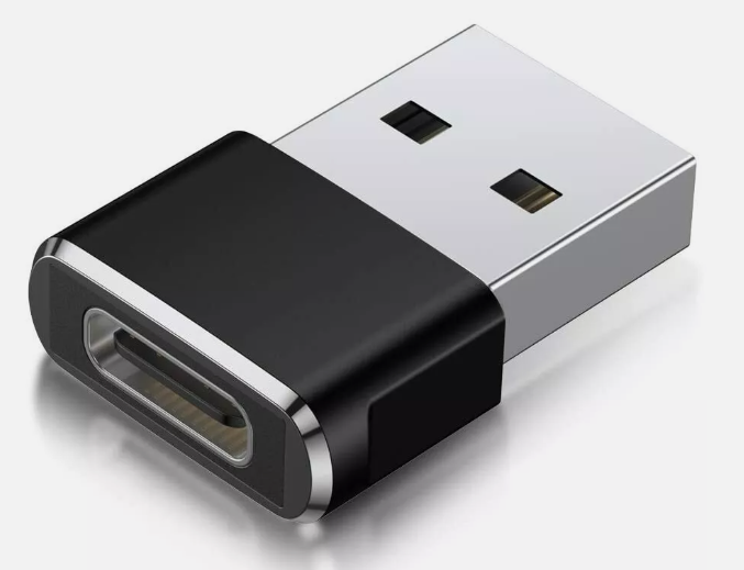
Figure 1: USB A to C adapter
Instructions
- Remove housing, switch, and battery
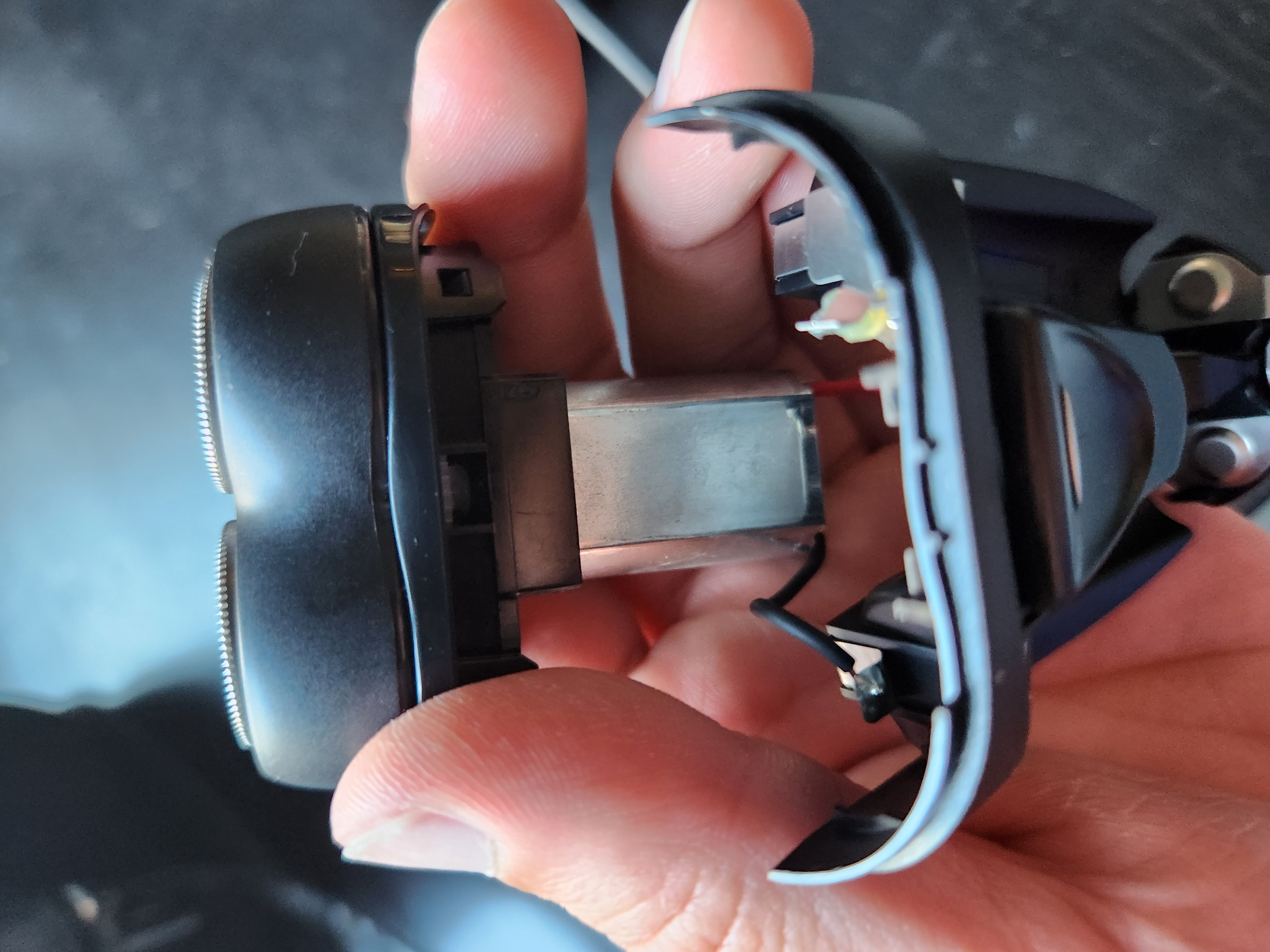
- Before removing wires to motor, mark which terminal is positive (red) and negative (black)
- Print case top, case bottom, and switch cover
- Disassemble usb C adapter
- Remove usb A connector shroud and housing around usb C port
- Install USB C adapter into housing
- USB adapter needs to be installed first before soldering to it
- It is recommended connect USB C cable to adapter and use a multimeter to verify polarity of power on USB A side
- Set output voltage on voltage converter
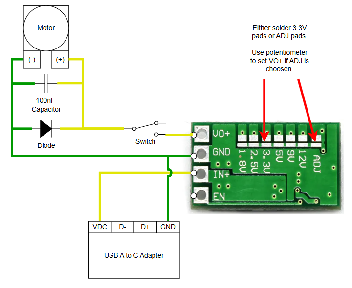
- The target voltage is 3 volts. Use solder to connect the pads of either the 3.3V or adjustable (ADJ) option.
- If ADJ is selected, hook the voltage converter to a >5 volt power source and measure the output voltage with the multimeter. Use a screw driver to adjust the potentiometer until ~3 voltage is achieved.
- Mount electronics and solder together per the diagram below and reference photo
- Assemble other half of case, attached switch cover, and install screw