
TIME: A 3D Printed Clock
We calculate the final price from your selected file. You review and accept it before payment.
Saved on this device.

A clock with a 3-day run time and a 1-second tick/tock pendulum - made to be as easy to build as possible.
- Rating
- 4.75 / 5
- Likes
- 536
- Downloads
- 1,123
- Makes
- 4
- Views
- 12,912
- Reviews
- 4
Updated at source:
Model information
- Source
- Printables
- Category
- Mechanical Parts
- License
- Creative Commons — Attribution — Noncommercial
This is the first release of TIME: A 3D printed clock, designed to be as easy to assemble as possible using readily available parts. This initial release should be regarded as a work in progress, with the instructions and files evolving over the next few weeks as the first builders make one - see the Notes and Add-Ons Section at the end of this post for the latest updates.
Parts are designed to be swappable to facilitate edits and upgrades. You can read an in-depth post on the clock over at https://digitalurban.substack.com/p/time-an-open-source-3d-printed-clock?r=u7cv . This page provides all the .stl files and details on how to make the actual clock.
If you like this, then clicking the ‘Like’ button would be really nice and encourages us to develop it further.
As with all 3D printed clocks you will need a few extra parts - we have kept them to a minimum and made them easy to source, the links below are Amazon UK, but the parts can be found with ease online:
683ZZ Ball Bearing 3mm x 7mm x 3mm Double Shielded 683-2Z Deep Groove Bearings, Carbon Steel (Pack of 10 - but you need 2 of them)
624ZZ Ball Bearings 4x13x5mm (Pack of 10 - but you only need 1).
Round Steel Metal Rods, 3mm x 60mm High Speed Steel (HSS) Lathe Bar Stock Tool, for Shaft Gear Drill Lathes Boring Machine Turning Miniature DIY Craft (Pack of 20, but you need 3 for the clock)
Brass Rod 3mm, Metal Round Brass Pin Bar Rod Length 100mm, Brass Rod for DIY Crafts Projects (Pack of 30, you need 2 - but as with all parts, these are good to have to hand if you plan to make other clock designs).
M4 (4mm x 8mm) Phillips Pan Machine Screws (Bolt) - Stainless Steel (A2) (Pack of 20) DIN 7985
Amazon Basics Neoprene Dumbbell Pair (these are the weight for the clock - in a perfect world the clock will run on 1kg - the link is for 2kg for the first build to get over any initial friction, but going down to either 1.5kg or 1kg is preferable). Again its good to have a few different weights on hand if designing a new clock or changing the runtime.
M4 Washers, M4 x 9mm Metal Flat Penny Washer Thickness 0.8mm- A2 304 Stainless Steel Washers (50 Pack - but you need 3).
1 Metre Dowel Beech Wood Smooth Rod Pegs - Craft Making DIY Hardwood Dowels 1m Length (you need 2 of them - at the moment these seem out of stock, any 1 Metre 10m Dowels, if you need a smaller size we can simply swap in a new part to the pendulum).
Print and Assembly

Part One - The Gears (Time Required - 5 Minutes)
Print the Base Plate, the first 3 gears and and the three gear holders:

The gear holders screw into the base plate with the M4 x 8mm screws.
Line up each gear and slide in the Round Steel 3mmx60 mm metal rods, give them a gentle tap to secure in place. All three gears should spin freely.

Well done, that is part one made and you should have 3 spinning gears.
Part Two - The Hour - (Time Required - 10 Minutes)
The second part involves putting in place the main hour gear - the metal rod is a close fit as it turns the hour hand - push fit in one of the smaller (7mm) bearings in the base plase (as seen above) and screw in place the Hour and Drive Holder. Push another bearing into the top and slide through a 3mm Brass Rod. This is perhaps the most fiddly part of the clock as need tapping in with a hammer and this aligning - it should not need much force. All four gears should now also be spinning freely.

Part Three - The Drive - (Time Required 1 Minutes)
Part three builds the drive, which is made up of three seperate components - the Drive Gear, the Rachets and the Pawls. First up we fix all 6 Pawls into the Drive Gear using the M4 bolts.

The pawls should move freely, as they work with gravity to hold the ratchet system in place. The Rachet is where our fishing line goes, to wind the clock. You need two cut lengths, approximatly two metres long. There are two holes, feed one from the bottom and one for the top and tie off with a knot. Its good to wrap up the line on the outer coil now as the Winding is still a slight work in process. This is where the weight will attached to - it should be wrapped around anticlockwise as it hangs on the left of the clock.
Dont get to frustrated at this point, you will get the hang of how it works and winding will become second nature.
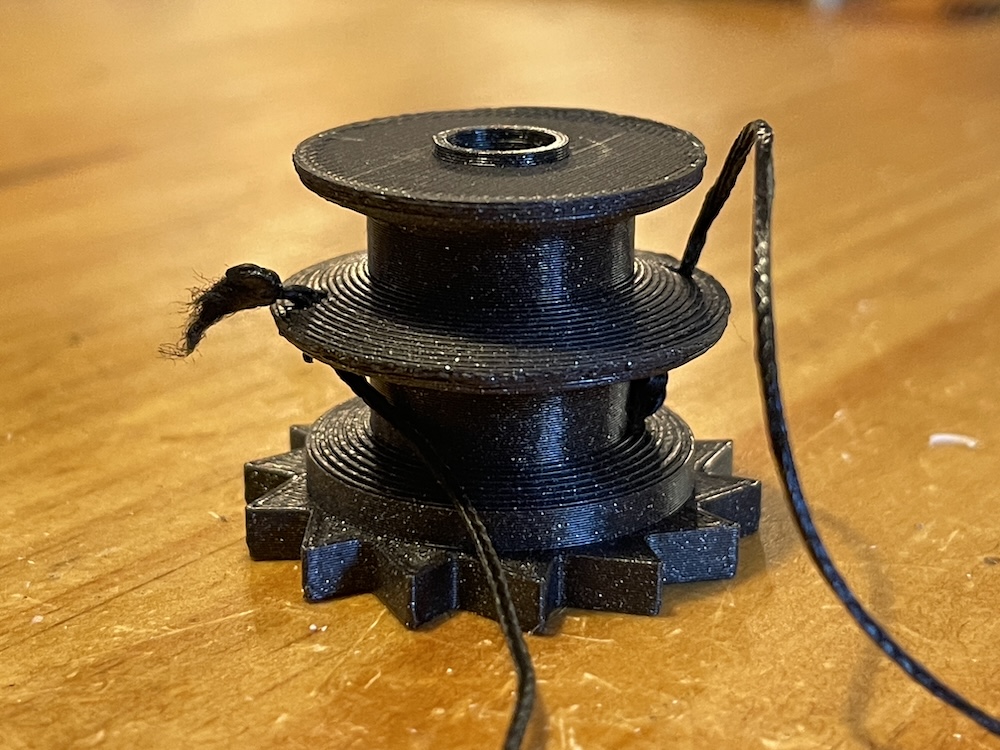
Pictured below is the Rachet with the line wound up (if it comes unwound dont worry too much, you can wind it back on later).

The Ratchet is now ready to be slotted ont the main drive and inbetween the pawls - making it ready to fit into the main clock.

Life the Drive and Rachet and slide into the main frame from the left, then align with the holes and fix in place with a 3mm Brass Rod, its a lose fit so it should easily slide in.

Make sure again that all the gears spin smoothly, all we need now, before we test everything is working, is to attach the Anchor and Pendulum holder.
Part 4 - The Anchor and the Pendulum Holder (Time Required 5 Minutes)
Push fit a 13mm bearing into the back of the Anchor and screw in one of the M4 bolts into the pendulum holder.

Now flip it over, slide the pendulum holder over the anchor and tighten so you can still move the pendulum holder, but with a bit of friction - this allows us to change the beat of the pendulum to acheive a regular ‘tick tock’ sound.

All we need to do now is to add it to the main clock base - after that we are ready to attach the main pendulum and hang on the wall for our first test (if all goes well, it should ‘just work’).
Use an M4 bolt through the bearing to fix the anchor to the main base board (this can be fiddly so i hold the bolt on the screw diver and then quickly pop it in).

It is also with attaching the lid of the weight holder at this point as we are almost ready to hang the clock for our first run. All we need do now is mount it on a piece of wood - this aids hanging and makes it easier to keep the clock level on the wall. For this we need 3 wood screws.

You can see from the photo that we have also added the bottom line holder (the white and black pole) - this is not essential at this point, its inlcuded as to make these instuctions we took a working clock apart… You can now hang the clock on the wall - all we need is the actual pendulum and the weight.
Part 5: The Pendulum (Time Required - 5 Minutes)
The pendulum is made up of two wooden dowels - one 1m long and another cut to 25 centimeters. They are joined using the 3d printed Joiner, under which slides on the Pendulum Bob. This moves up and down to fine tune the timings of the clock, once it it running (we normally do this last).

If you have the clock hung on the wall the pendulum should gently slide into the pendulum holder.
You can now put in the 2kg weight into the weight shell and screw it onto the lid - you are ready to go, give the pendulum a nudge and see if it ticks.
You are looking for a smooth ‘tick tock’ sounds - adjust the pendulum holder slightly either way to get the correct rythum. This normally takes a couple of minutes to get correct.
If you clock is running then leave it on the wall and see how long it runs. If it goes for more that 15 minutes you can move ont the final step, attaching the hands. If it stops then check your clock is level (horizonally and vertically) and make sure all the gears are free to move. Any problems - let us know in the comments and we can trouble shoot.
Part 5 - Attaching the hands and the face (Time Required - 5 Minutes)
The hands fit on the front of the clock via an additonal section of brass rod that pushes in - to make this simply cut a 15mm section off a 3mm brass rod strip and push it in.

Pop a washer over it and slide on the Minute Drive (the larger gear) and the Hour small gear.

After that slide over the Hour Front Gear and clip in place the hour hand. The Minute hand slides over onto the brass rod, securing the mechanism.

The Clock Face simply attaches with a final M4 bolt and with the additional of the TIME words, you are done…

We hope you enjoy the clock - do let us know if you build one as we would love to see it and if you could please do give us a like or a share for the model…
A Note on Slicing
The Gear Holders require slicing with supports (we put the front face on the bed to ensure a perfect hole - side ways would perhaps seem more logical but it does not seem to work as well with the front hole losing its shape, we are open to thoughts on the best way to slice). The supports do come away with easy, leaving perfectly shaped holes for the gear rods.

The Drive and Hour gear holder requires support from the base and should be printed at 0.1 resolution for improved hole created. Print time is approx 4 hours.

Finally - on the main base of the clock we have used supports - this does require picking supports out of the bolt holes but it provides a clean surface for the gear holders to fit into - if you dont want to bother unpicking then you can get away without using supports.

Add Ons
The clock is made so parts can be swapped in and out as it develops - this is via a series of add-ons, easy-to-fit parts which enhance the clock, while also keeping it as simple as possible to build. The first of those is a winder mechanism - if you are new to making TIME, we do recommend swapping the original Ratchet and Gear 3 Holder for these parts - our clock ran first time with these new additions in place.
The Winder and Key
The Winder addon notably improves long-term reliability of the clock. It reduces the winding cord to a single thread, allowing a much smoother cord thread and limiting any tangles which could stop the clock. It is also easy to make with a new ‘Winder Rachet’ and a direct replacement for Gear Holder 3 - Gear_Holder3_WinderVr2.stl. The final addition is a small Winder Gear onto which a new Winding Key attaches - see the image below with the winder in place:

The Winder Gear attaches to the new Gear_Holder3_WinderVr with an M4 bolt and a washer - it needs to be tight enough to avoid any wobble but still turn.
The new Winder Ratchet comes in two parts which simply screw together - this avoids any glue or additional screws and improves the print quailty to avoid any support structures. The parts are WinderRatchet_Gear and WinderRatcher_Base . It has a hole where you can thread your winding core and tie off - this goes to your weight.

The new Winding Ratcher simply replaces the previous Rachet and slots in the same way, the final part if the key.
The Key comes in four parts (Key_Body, Key_Shaft, Key_Ring and Key_BaseRing, all of which screw together:

These parts allowing it to fix onto the Winding Gear and spin while winding - this lifts the weight and winds the clock. Note - it winds Anticlockwise…

Finally, we added a Hook option, to save screwing/unscrewing the weight lid when you want to add or remove the main drive weight.

Additional Notes
As we further refine the model (as all models are a work in progress) we will add notes here with updates, remixes are encouraged, we will provide the raw Fusion files once they are cleaned up and if there is demand.
8th August 2025 - Updated Gear 2 (eliminates a small wobble).
11th August 2025 - Updated the Clock Base - moved the Escapement and Anchor across by 1mm - this ensures a more reliable build. Now Clock_BaseV1_1.stl
14th August 2025 - Added a new version of the HourandDrive_Holder - V2. This adds an additional screw hole at the bottom to keep the clock flush to the wooden mount. Its not required if you have already printed the first version, but is a nice update to have.
15th August 2025 - Uploaded a new slightly smaller version of the words TIME - they are push fit - this will be determined by your own printer so resize by 1 or 2 % as needs be.
The new winder is working well - I will let it run for 3 days, check the rewind opertation and then upload, its a quick swap to add to the exisiting model.
16th August 2025 - Added the Ratchet which was accidently missed out of the original files and the Cord Ring Pull - this ties to the lose end of the cord (to pull it up).
A TIME: The Hour Bell version is being developed, based on our Pomodoro timer (see this post for more details). Its not the most flexible system - at the moment you need to set the hands and start it on the hour - but we thought any makers of the clock might like to see a possible future ‘add on’.

August 21st - Published the Winder and included an Addon section to these build instructions.
As a side note, the Strike Bell is now working well and complete, it will be included soon as another add on (and its really easy to add). If you would like to order the parts, ready for the bell files to be released you need:
- 4mm x OD 13mm x Width 5mm Miniature Bearings (they come in a pack of 10, you need 2, they are a generic size and are widely available);
- A Counter Bell / Reception Bell - Again available via many outlets - 85 cm/3.5 inch base.
August 29th - Added Key_Holder.stl - to hold the key. The bell add on is working well on a 2.5kg weight, files will be released soon.

October 16th - Klaus505 has noted over at his excellent remix that the use of Carbon Fibre Rods reduced the weight required - we have just tried it out using these rods (cut to size) and can confirm they are excellent, allowing the clock to run on a 1kg weight (or even less). Thanks to Klaus.
Any questions or issues, let us know in the comments.