
InMoov Petit (Part 2 of 10) Chest, Shoulder and Arms
We calculate the final price from your selected file. You review and accept it before payment.
Saved on this device.

InMoov Petit (Part 2 of 10) Chest Shoulder and Arms
- Rating
- 0 / 5
- Likes
- 7
- Downloads
- 46
- Makes
- 0
- Views
- 311
- Reviews
- 0
Updated at source:
Model information
- Source
- Printables
- Category
- RC & Robotics
- License
- Creative Commons — Attribution — Noncommercial
Assembly of the InMoov Petit
MG90S Servos are used for the Arm Servos (Use exclusively Metal Geared Servos they are recommended for longevity of operation).
Print and Trim all the STLs, and prepare them for assembly , a game changer for me is a rotational blade tool, it easily removes brims and excess plastic, it is way safer than a knife btw.
Start with the inner Shoulder-servo mount V2_InMoov_Petit_ShoulderServoBracketLeft.stl
Glue a servo horn into the base of the Servo carriage , see below

The trick is to use some grease-proof paper , slide this with the servo into the carriage abd then glue the servo horn into the gap provided and press the servo horn down against the greaseproof paper, let it cool and it easily pulls out peels away from the servo within
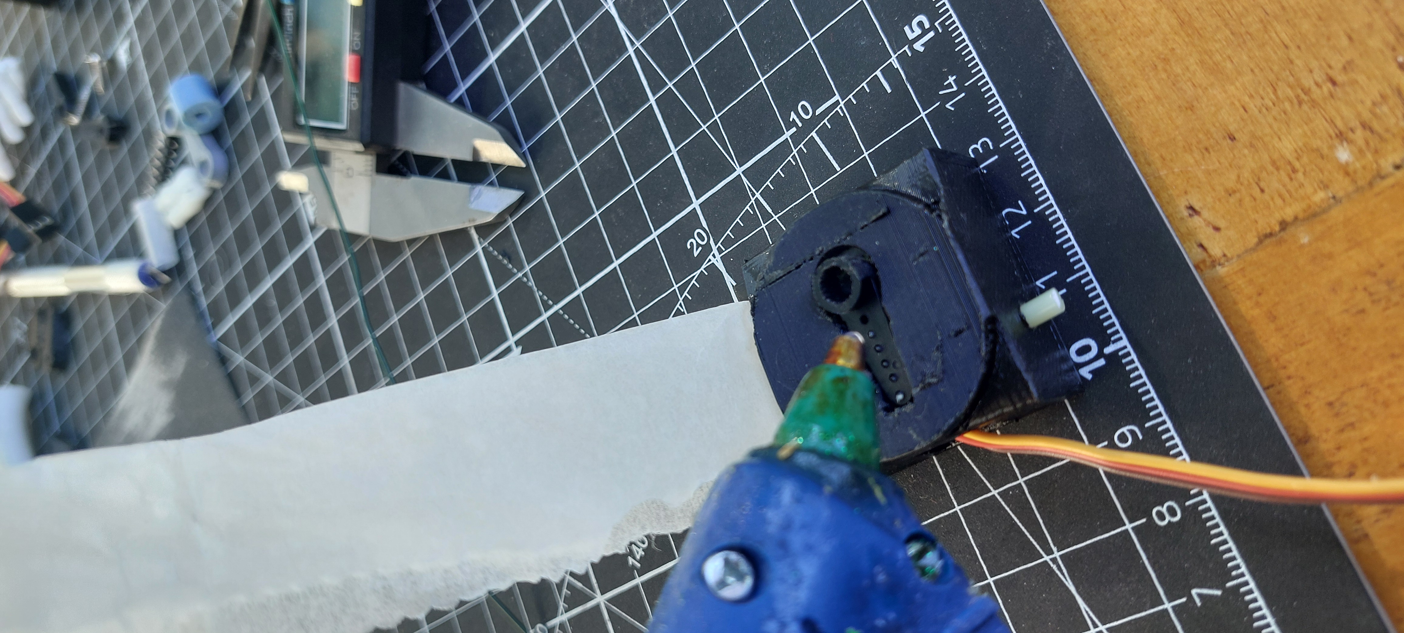
Slide it into the carriage and screw down with servo screws
This piece is a pivotal part of the shoulder , to mount it to the chest you will need to place a servo blank into the Front chest piece, also a 5mm cut off of 2.85mm PLA or that slots into a hole on the Shoulder Servo bracket (there is a small hole that you can press the pla into), this forms a pivot point for the servo.

Next comes the Shoulder rotation Servo mount, glue a servo Horn into the base of the unit.

Now for the upper and lower arm :-

Cut the small triangular bit off the print, this is not needed and was put there so that the print does not need any vertical supports during printing (dont cut the round spigot part, that is needed as a pivot point for the lower arm), next glue (yes Glue) a servo into the Upper arm servo carriage

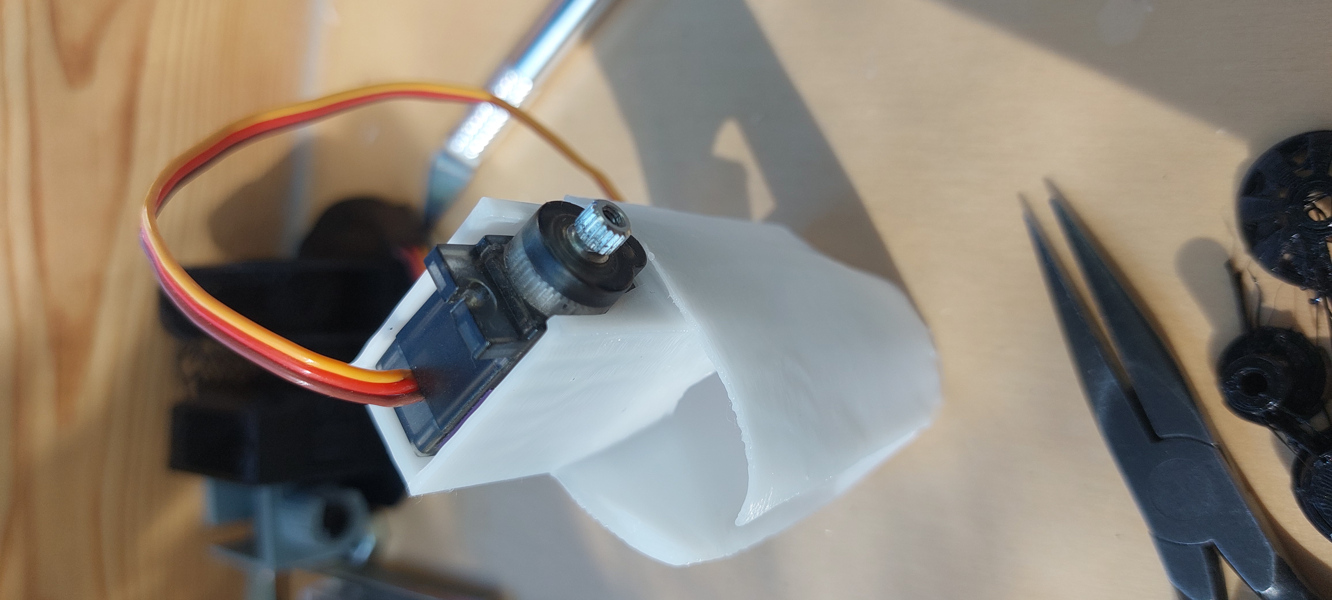
Also glue a Servo horn into the lower arm servo horn port.

The Chest Plates are marked Front and back, presently they are bolted together with some M6 nylon bolts (spacers will eventually be designed, as soon as I have determined the chest volume).

