MPR&P-V2... a Mostly-Printed Rack&Pinion CNC Machine
We calculate the final price from your selected file. You review and accept it before payment.
Saved on this device.
Model information
- Source
- Printables
- Category
- Tools
- License
- Creative Commons — Attribution — Share Alike
This is version 2 of the MPR&P 3-axis CNC machine. It is highly modular - comprised of three near-identical linear stages and two identical lift stages. This version of the MPR&P is a completely original design but was heavily inspired by V1Engineering's popular LowRider4 "beam and lift" setup.... which has repeatedly demonstrated outstanding rigidity for a DIY machine. This design has also been openly developed in a thread on the V1Engineering forum, found here:
https://forum.v1e.com/t/mpr-p-v2-engineering-really/52338
It consists of both printed parts and common hardware that is both inexpensive and readily available from local sources or online... no expensive or hard-to-get specialty parts are required.
Unique to this machine are printed herringbone rack-and-pinion (R&P) for the linear stages and printed leadscrews for the lift stages. The leadscrew for the lift stage is the only part needing support (organic/tree works well) and is printed-in-place, vertically... and the support nut/collar is then discarded. The racks are made up of easily printable rack segments that are strung together on 1/4" threaded rod and used to set the length of an axis to most any practical length. The other fastening hardware consists of 5/16" (8mm) hex bolts of varying lengths up to 7" or 8" from the big-box store and an assortment of M3, M4, and M6 machine screws and nuts. NEMA17 stepper motors, suitable wire, lever wire connectors, and an inexpensive Arduino-based GRBL controller are the electrical/electronic parts used in this machine... easily found online from various places, including Amazon.
Here the MPR&P is pen-plotting 100mm rulers to check for accuracy and backlash.
The printed leadscrews are lifting more than 16 lbs. in this early test of the lift stages.
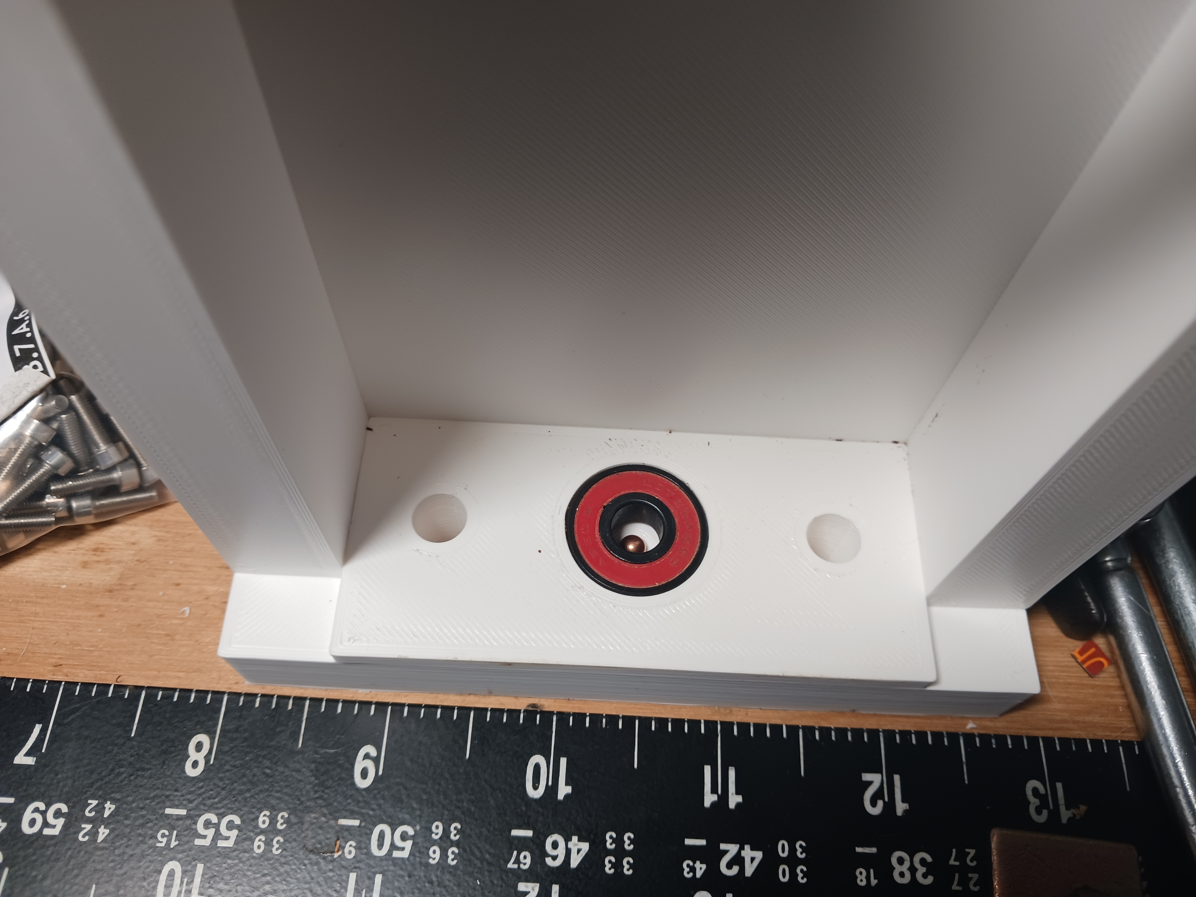
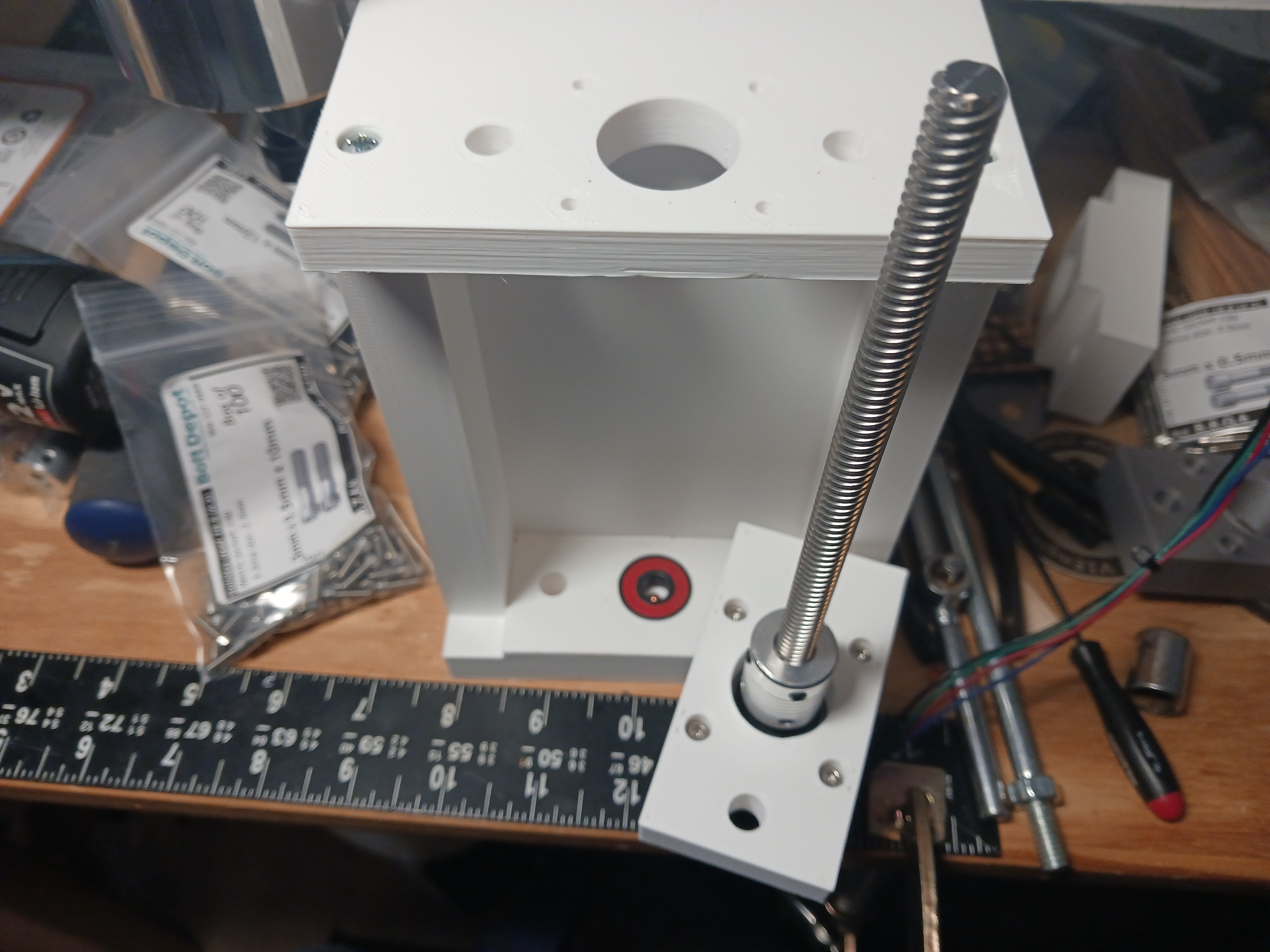
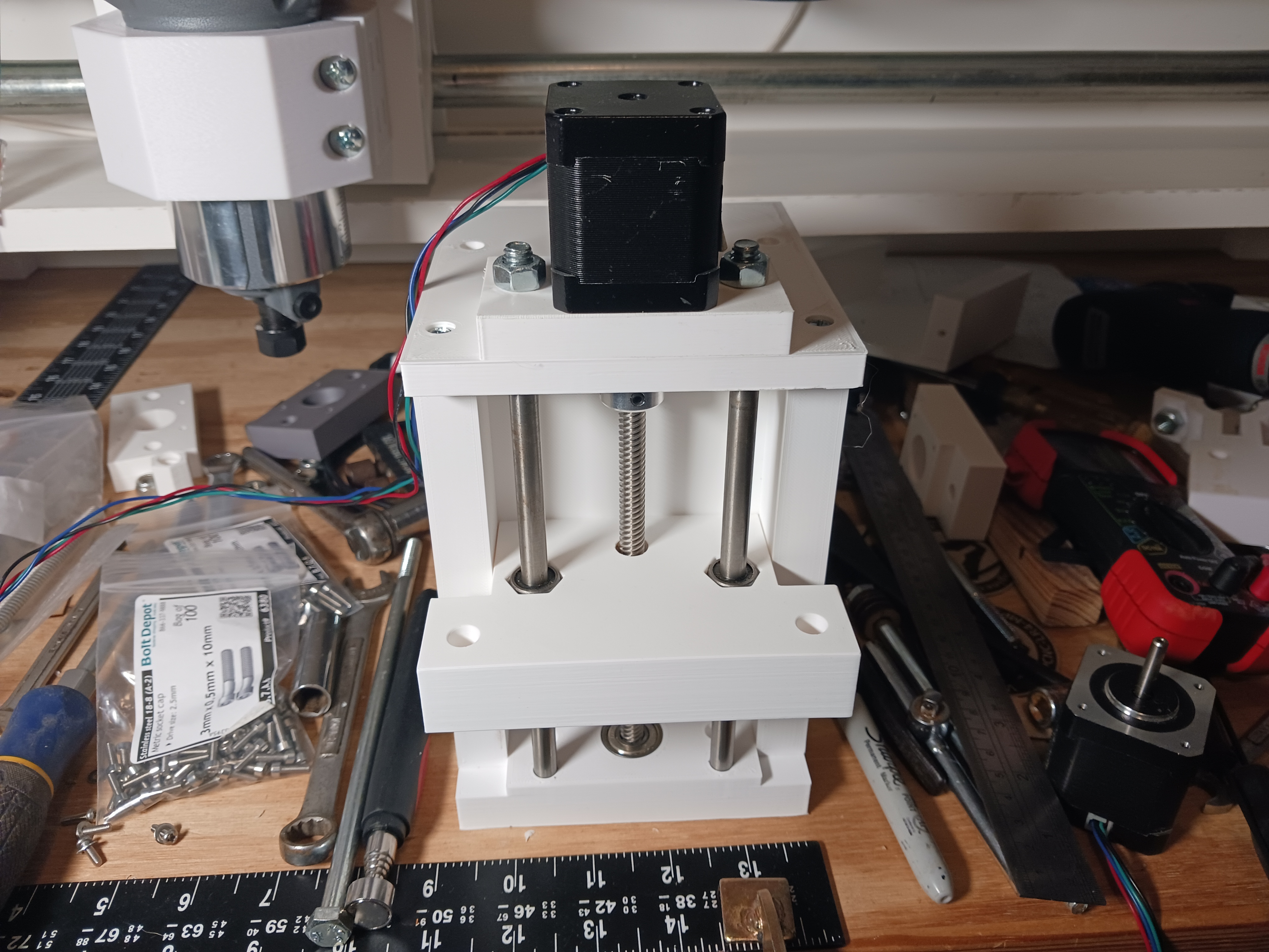
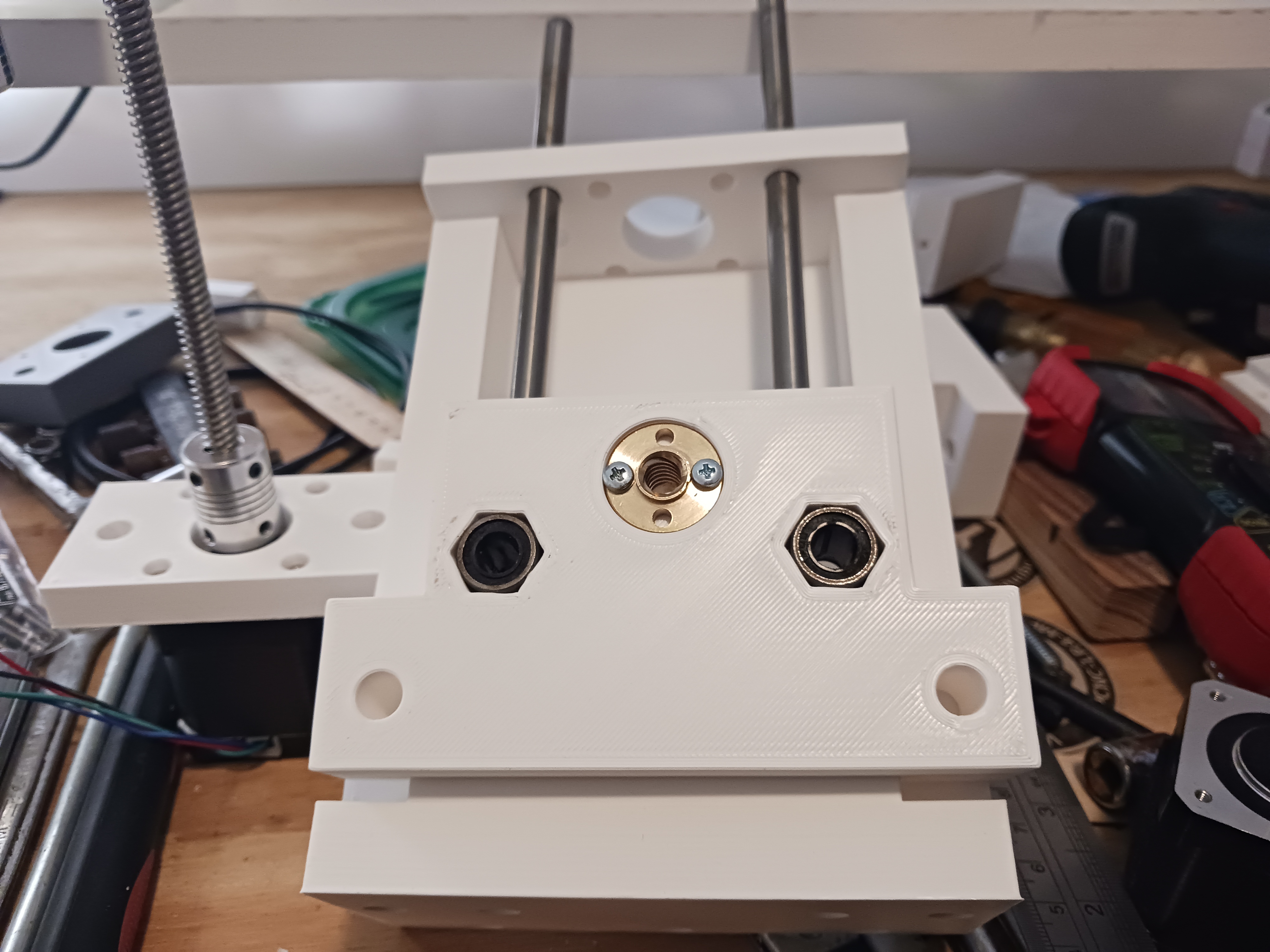
Edit - 02/01/2026: The printed Z-lift leadscrew never performed reliably enough for long enough for my satisfaction. I went to a 150mm long T8 leadscrew, 8mm to 5mm coupler, and 8mm polished guide rod and 24mm long LM8UU linear bearings... all scrounged from a discarded 3d-printer. Even new, these should be inexpensive and readily available from online sources.
One small detail: There is a BB placed in depression in the capture_plate to support the bottom end of the T8 leadscrew. Adjust the coupler's grub screws to allow the leadscrew to rest on this BB.