
Self-Orienting Ratchet Socket Wrench 2.0
We calculate the final price from your selected file. You review and accept it before payment.
Saved on this device.
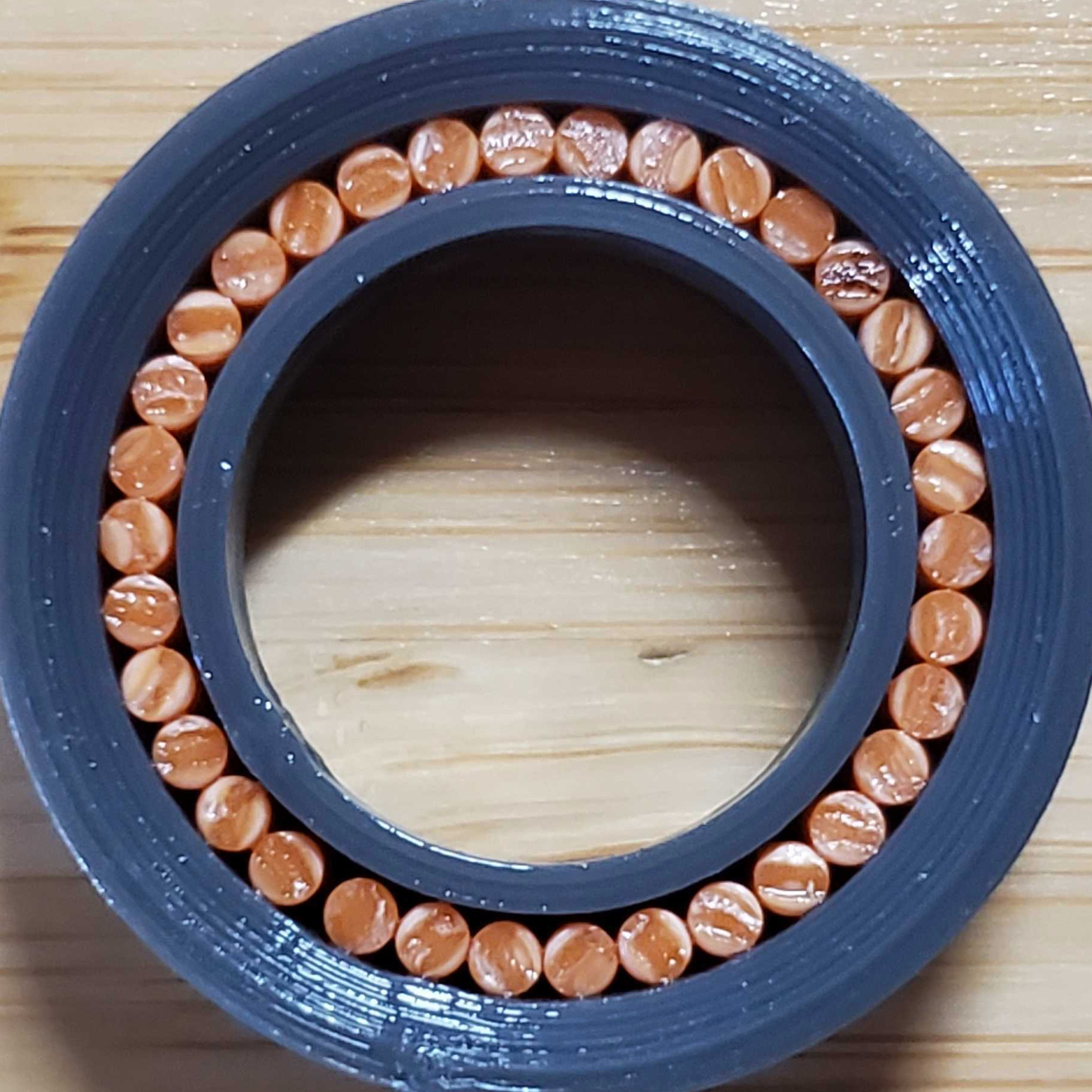
This is an update to the original wrench. New switch placement and beefier pawls.
- Rating
- 5 / 5
- Likes
- 63
- Downloads
- 239
- Makes
- 1
- Views
- 1,842
- Reviews
- 2
Updated at source:
Model information
- Source
- Printables
- Category
- Other Toys & Games
- License
- Creative Commons — Attribution
Version 2.0 is here! This socket wrench chooses the correct ratcheting direction on its own when you start using it! All you need to do is reset it with the switch afterwards. Gone are the days of ratcheting the wrong way!
Printed with 0.15mm clearances and 0.2mm layer height, 10-20% infill for all parts.
2 walls and 4 top/bottom layers. Elephant's foot is a big issue for this design, make sure your printer is well-calibrated. Of course, print each part on its flattest face. If you have issues with fitment, reaming out holes and shaving off bulging corners is recommended.
IF YOU HAVE ALREADY PRINTED VERSION 1.0, ONLY THE CAP, PAWLS, SMALL PIN, AND SMALL PIN KEY ARE NEW.
Assembly:
- Insert both halves of the BIG PIN into the larger hole in the FRAME.
- Press the ANVIL onto the BIG PIN, making sure to align the through holes.
- Insert a 1 inch length of filament all the way through the holes to pin the ANVIL to the BIG PIN. Ensure the filament pin sits centered and does not stick out into the teeth. This step is difficult to reverse.
- Insert the SMALL PIN KEY into the small hole in the FRAME. This will require a good push to get the key through. Then, insert the SMALL PIN into the same small hole to complete the Switch. Rotate the Switch so that the key points toward the handle.
- Press the PAWLS onto the SMALL PIN and SMALL PIN KEY, making sure that the key meshes with the keyway in the PAWLS. Also ensure that the two middle pawl arms are spaced apart by two ANVIL teeth when centered.
- Press the CAP onto the FRAME, making sure that the handle end of the FRAME sits snugly in the CAP channel. The ANVIL, SMALL PIN, and SMALL PIN KEY should fit into their corresponding CAP holes.
- Slip the BIG RING and SMALL RING onto the ANVIL and SMALL PIN/SMALL PIN KEY, respectively. This will lock the head of the CAP to the FRAME.
- Insert lengths of filament through the three holes in the handle to pin the CAP to the FRAME. Snip off excess.
- Attach demonstration SOCKET if desired.