
MMU Feedback Tension Compression Sensor
We calculate the final price from your selected file. You review and accept it before payment.
Saved on this device.
Model information
- Source
- Printables
- Category
- Accessories
- License
- Creative Commons — Attribution — Noncommercial
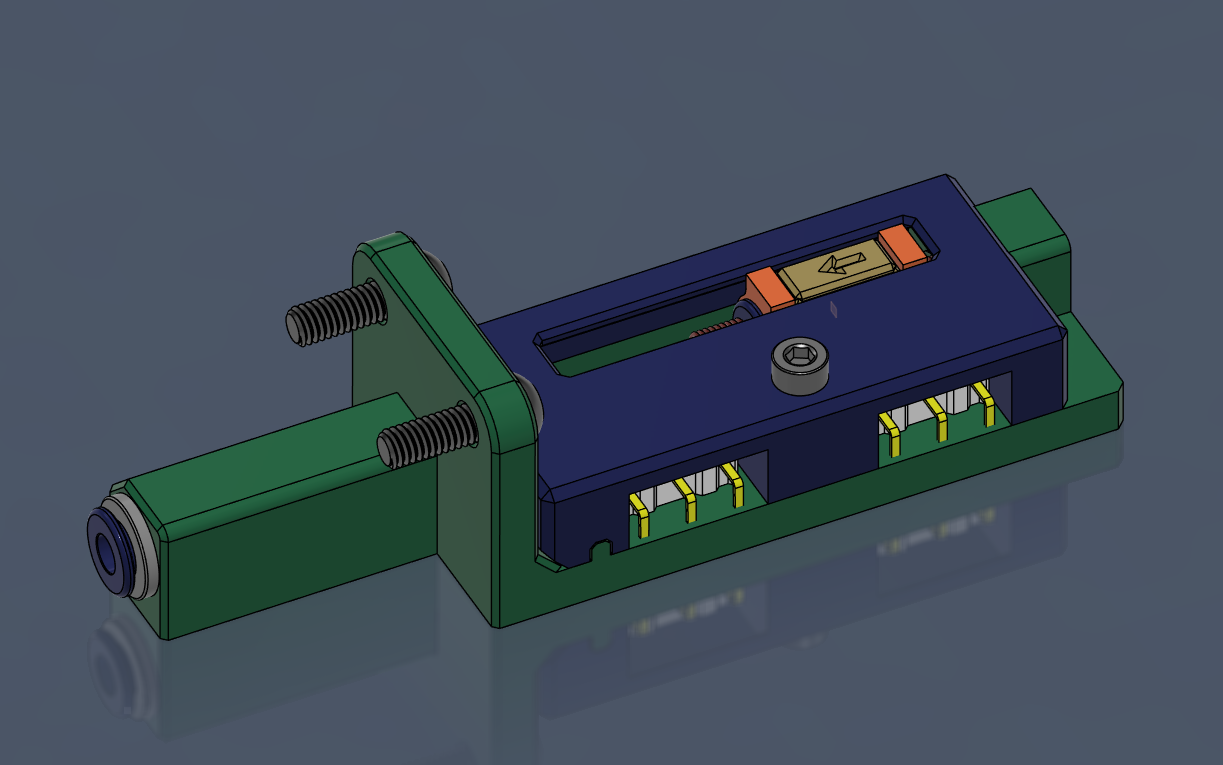
Welcome to my Feedback Sensor for MMU's
###### Please post your Makes ######
Please like this, download and post the make if you built it
It helps us makers with feedback and gets us some Prusa meters as most people don't pay it forwardFeel free to help my projects continue https://ko-fi.com/gcodegearhead
############################################################################ Intro ###########################################################################
I needed a multi lane feedback sensor for my Low Rider MMU due to the way it parks independant lanes right outside the toolhead. See my toolhead XOL-Metrix UHF for the SV08
This is a remix of the Box Turtle Turtle Neck from Armored Turtle.
It is functional I will post updates as and when needed.
############################################################################ Update Log###########################################################################
DATE | Info |
|---|---|
24-MAR-202 | Initial Release. |
############################################################################ BOM###########################################################################
Part | QTY |
M3 x 14mm SHCS | 1 |
M4 x 14mm BHCS (or custom length) | 2 |
Heat Set Inserts M3 OD5 L5mm | 1 |
2 | |
ECAS 04 Fittings | 3 |
Spring OD=6mm L=18mm Wire Ø0.5mm | 2 |
Wire 22AWG or thicker | As required |
PTFE Tube OD 4mm | As required |
############################################################################ Assembly Instructions###########################################################################
Print the parts as oriented. No Supports required
I used 0.2 layer height with 4 walls 15 % gyroid.
Use the exact same limit switches
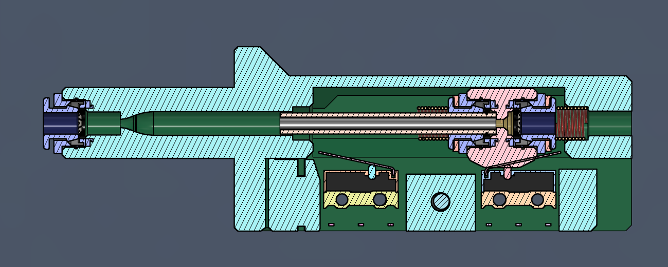
Assemble parts as per pictures and below section view.
The internal PTFE Tube is 37mm long
Note remove all black plastic parts from ECAS
The M2 screw holes are dependent on your printer tolerances.
Let me know if its to loose and I will upload a tighter option, don't over tighten.
############################################################################ Wiring ###########################################################################
You want to wire the switches in parallel and in the Normally Open condition. See pictures for wiring.
Wire the two grounds together so that you only have 3 wires exiting the sensor.
Happy Hare Changes
mmu_hardware.cfg |
|
mmu_parameters.cfg |
|
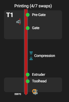
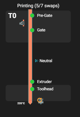
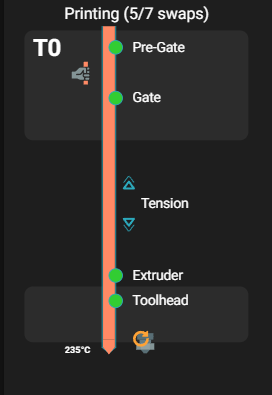
When enabled and working you will see a “Compression” , “Neutral” or “Tension” symbol in the MMU Panel
 |  |  |