
3/4 Scale Thunderbolt 1000T Core
We calculate the final price from your selected file. You review and accept it before payment.
Saved on this device.

Early access release of my new and improved thunderbolt.
- Rating
- 0 / 5
- Likes
- 1
- Downloads
- 19
- Makes
- 0
- Views
- 211
- Reviews
- 0
Updated at source:
Model information
- Source
- Printables
- Category
- Mechanical Parts
- License
- Creative Commons — Attribution
Early access release of my 3/4 scale thunderbolt core. Currently only 5/6.
Print the motor holders and rotor at 100 percent infil for best results.
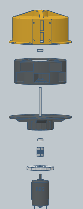
Use supports on everything.
Get a high RPM 895 DC Motor. Thunderbolts run about 7000 RPM so a 10000+ RPM motor will be perfect. Here are the ones I use: ZVKV 2 Pcs 895 DC Electric Motor 12-24V 10000-20000RPM High Torque Adjustable Double Ball Bearing Motor for DIY Small Drill Micro Machine Tool - Amazon.com
Press a 16mm OD, 5mm ID bearing into the hole inside the chopper cap. Use a bit of superglue on the outside of the bearing to make sure it doesn't come loose. But not too much, you don't want it to seep into the bearing and ruin it. Also press one into the hole inside the top motor holder section.
These are the correct bearings, however, any bearing with the same dimensions will work: uxcell 25pcs 625ZZ Deep Groove Ball Bearings 5mm Bore 16mm OD 5mm Thick Carbon Steel Double Shielded ABEC3 Z1 Bearing for Motors: Amazon.com: Industrial & Scientific
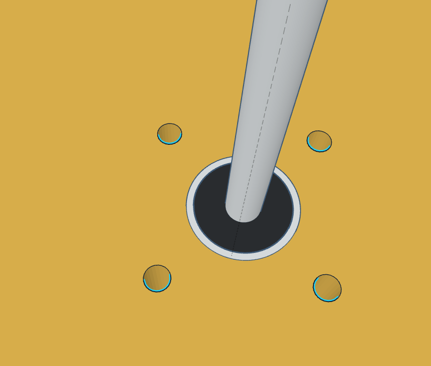
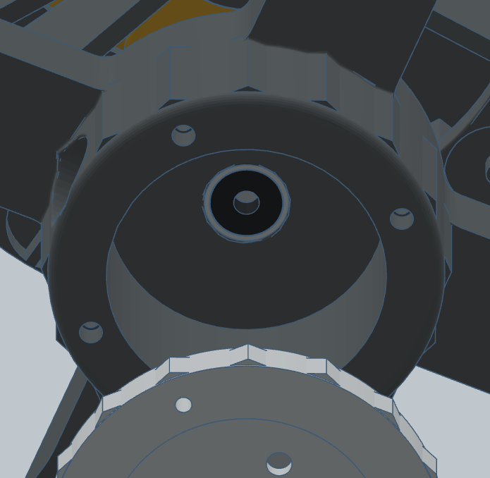
Once your bearings have set, screw your 895 DC motor onto the lower part of the motor holder assembly, putting the motor into the part that is sunk in, so the flat part faces upwards away from the motor.
Then, put a 5mm to 5mm flexible shaft coupler onto your motor's shaft. ensure it is tight, as 895s have a stupid amount of torque and can slip inside the coupler if not properly tightened. The model is best optimized for this specific coupler, but any 5mm to 5mm flexible coupler will work: Amazon.com: Saiper Flexible Couplings 5mm to 5mm (5pcs) Aluminum Alloy Joint Connector Compatible with NEMA 17 Stepper Motors, RepRap 3D Printer or CNC Machine, 3D Printer Accessories : Industrial & Scientific
Once you have verified the coupler is properly connected, put M3 heat threaded inserts into the 4 bottom holes of the top motor assembly.
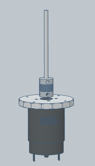
After your inserts are set, insert a 5mm x 100mm metal rod into the flexible coupler. Make sure it is very tight, as it is the shaft that spins the rotor. Your assembly should look like this ------------------------------------------------>>>
Any 5mm x 100mm rod will work, but these are the ones I found: Amazon.com: MewuDecor 5mm x 100mm 304 Stainless Steel Round Rod, Metal Solid Shaft Rods for Industry, Metal Working Hobbies and DIY Craft, 5 PCS : Industrial & Scientific
After you have verified it is all properly connected and tightened, insert the rod through the bottom of the top motor holder and through the bearing. Connect the lower assembly to the top with M3 screws. Your final motor assembly should look like this. (THIS MOTOR ASSEMBLY WILL ALSO BE CROSS COMPATIBLE WITH MY FUTURE LARGE SCALE MODELS!!!!)
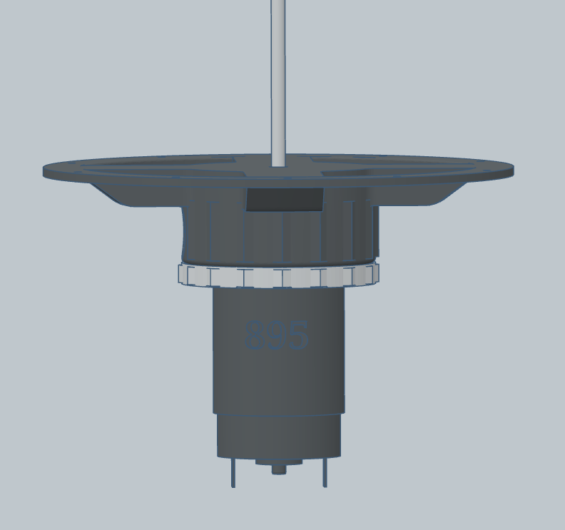
Once your motor assembly is assembled and you have verified it works, print out your rotor/chopper.
100 PERCENT INFIL IS REQUIRED!!!!
Or if your one of those people. 95 percent is okay. 🤓
Use supports on the whole rotor if possible, anything being warped or out of balance isn't good at this scale.
Once your rotor is all printed and prepared, insert 10 gram slotted weights into the bottom of the rotor into their slots. These are the ones you need. :QWORK Lab Slotted Mass Set, 4 Set of Chromium-Plated Metal Slotted Weights, Each Set - Total 100g - Includes 9 Weights (10g Each) & One Hanger (10g): Amazon.com: Industrial & Scientific
Put a little tiny drop of superglue in the weight slots on the rotor if you want, just extra security.
Then, press a 5mm to 5mm solid shaft coupler into one of the slots on the rotor, making sure the set screw holes are aligned. A drop of superglue can go here as well. These are the ones I use, I'm not sure if the sizing and screw spacing is the same across other 5mm couplers: https://www.amazon.com/uxcell-Coupling-L20xD12-Coupler-Connector/dp/B07P6X9GSQ/ref=sr_1_5?crid=2V1QZ8EMZ5NGS&dib=eyJ2IjoiMSJ9.zEdyg_QpcvGWJCL_DJMoHKZ5f9rjhgNNEtSM2IjG9DqBhNQpHDj5xifdDtVJeW85zQMGkGVrqjIfV2jXFLS5HuI6JTzi2epUIdPLZOmXoCZVC7Dh4vPAnMxrDcecbbYScXqLsEVoW3UoEa4I4o-qGq8OrYr2HgUx11G6P6NaTYvYmqVx2EBo5DQxYdT6Ecoa0OMbl06anJaq3kUfs1KFByAYyZhNLfngVDP8wVNuXDk.brDyxFLQvtvzs70fcv3cvY436OgKj-Z7L6n0EVA42DQ&dib_tag=se&keywords=5mm+to+5mm+shaft+coupler&qid=1780638799&sprefix=5mm+to+5mm+shaft+coupl%2Caps%2C238&sr=8-5
Then, put your rotor onto the shaft, and tighten your set screws in the coupler to secure your rotor. Give it a hand spin. Many of them. Enjoy your new fidget toy.
Once you have finished messing around, put your chopper cap onto the top of the motor assembly. Make sure you align your shaft and into the bearing. Then, screw it in with M3 screws and nuts.
IF YOUR ROTOR SCRAPES, YOU CAN USE A LOW GRIT SANDPAPER ON THE ROTOR OR INSIDE OF THE CAP. This siren has 0.4mm tolerance, and not all printers are capable.
I don't really know what else to say other than merry happy birthday celebration of life or something. Enjoy your thunderbolt core. FULL MODEL SOON!!!!