
Filament width sensor (hall sensors)
We calculate the final price from your selected file. You review and accept it before payment.
Saved on this device.

Filament width sensor with hall sensors. It's based on https://www.thingiverse.com/thing:4138933
- Rating
- 3.8 / 5
- Likes
- 104
- Downloads
- 414
- Makes
- 6
- Views
- 6,804
- Reviews
- 5
Updated at source:
Model information
- Source
- Printables
- Category
- Accessories
- License
- Creative Commons — Attribution
The idea is based on https://www.thingiverse.com/thing:4138933
You need for V1 sensor:
2pcs small 623ZZ bearings (OD:10mm, ID: 3mm, W:4mm)
2pcs small M3 washers (washer goes under bearing)
6pcs M3x8 screws
spring from an automatic pen
4Pin right angle male terminal
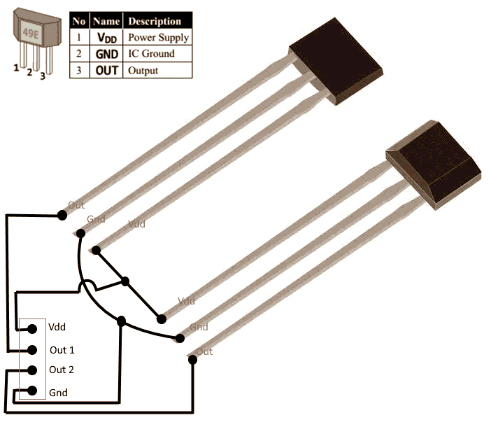
2pcs ss49e hall sensors
one 5x2mm magnet
wires
some tube connectors
The sensors are placed the same way as in the original design.
For configuration and calibration info please check the original thing.
I have connected it to BTT SKR V1.4 TFT socket (sensor1 -> RX0, sensor2 -> TX0, GND -> GND). Adc ports: P0.3, P0.2
Power for the sensors is taken from WiFi socket (3.3V)
Made a smaller version V3 of this sensor!
Instead of bearings, it's using 2pcs 5x8mm rollers (roller bearing rolling element)
STL files for that design will have suffix V3
Everything else remains the same.
Enjoy!
Print Settings
Rafts:
No
Supports:
No
Post-Printing
Use fine-grade sandpaper to finetune the arm sides. The arm should move smoothly in the groove. The filament holes must be adjusted by drilling (I was using ~2mm drill bit)
Sensor connection

Category: 3D Printer Accessories