
Metric Tolerance Gauge (M9 - M12)
We calculate the final price from your selected file. You review and accept it before payment.
Saved on this device.

A Metric Tolerance Gauge from 9 to 12 mm
- Rating
- 0 / 5
- Likes
- 3
- Downloads
- 15
- Makes
- 0
- Views
- 124
- Reviews
- 0
Updated at source:
Model information
- Source
- Printables
- Category
- Tools
- License
- Creative Commons — Attribution — Noncommercial — Share Alike
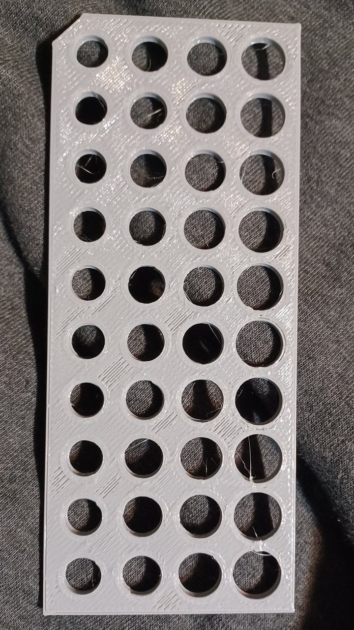
This part is inspired by superjamie's part on Thingiverse, which as far as I know is not here.
However, this Printable is not really a remix. I created the model from scratch in Fusion 360 (Jamie's is an OpenSCAD model) to cover a few additional sizes.
Hold the part as shown in the photo to the right: in Portrait orientation with the shorter side on top, the longer side to the left, and the corner that is clipped off diagonally to the upper left.
The columns then will be 9, 10, 11, and 12 mm in diameter. The top row are modeled to exactly those measurements, while the holes on each subsequent row are 0.1 mm larger than the hole just above them.
For example, the fifth row of the second column (10 mm) is 10.4 mm. If putting a bolt or other part in this hole gives it the correct fit, then you should size the holes for that part in CAD to 10.4 (assuming your printer prints consistent holes).