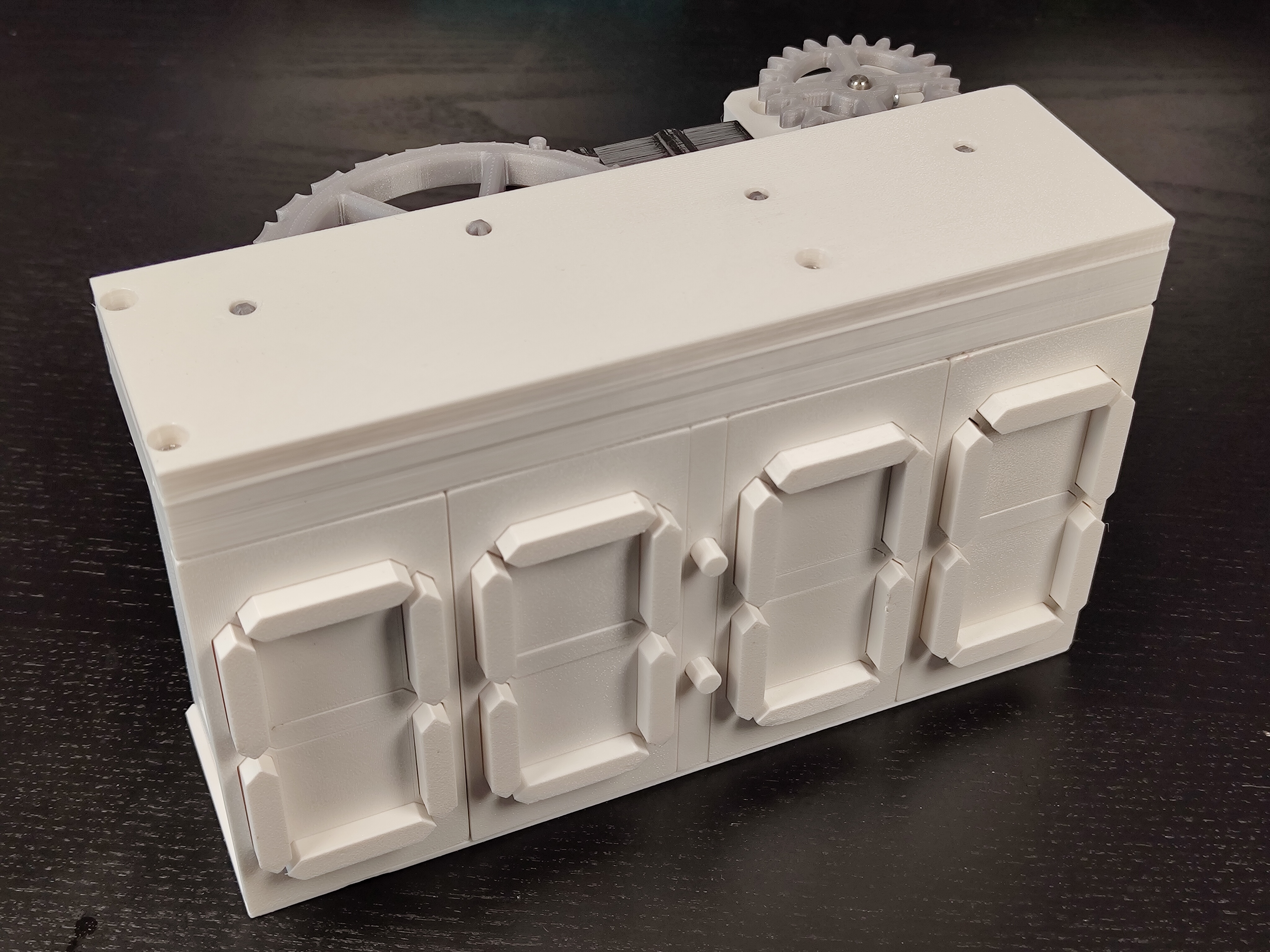
Mechanical Digital Clock (24 hours)
We calculate the final price from your selected file. You review and accept it before payment.
Saved on this device.

Mechanical digital clock based on four camshaft-driven seven segment displays
- Rating
- 5 / 5
- Likes
- 495
- Downloads
- 706
- Makes
- 1
- Views
- 12,915
- Reviews
- 1
Updated at source:
Model information
- Source
- Printables
- Category
- Engineering
- License
- Creative Commons — Attribution
This is a mechanical digital 24-hour clock. It is driven by a single motor (or by hand) and uses geneva drives and camshafts to display the correct patterns on four mechanical seven segment displays.
Non-printed parts
- 46x Square M3 nuts
- 50x M3x6 screws (or longer)
- Plastic glue
- Electronics (see below)
Digits
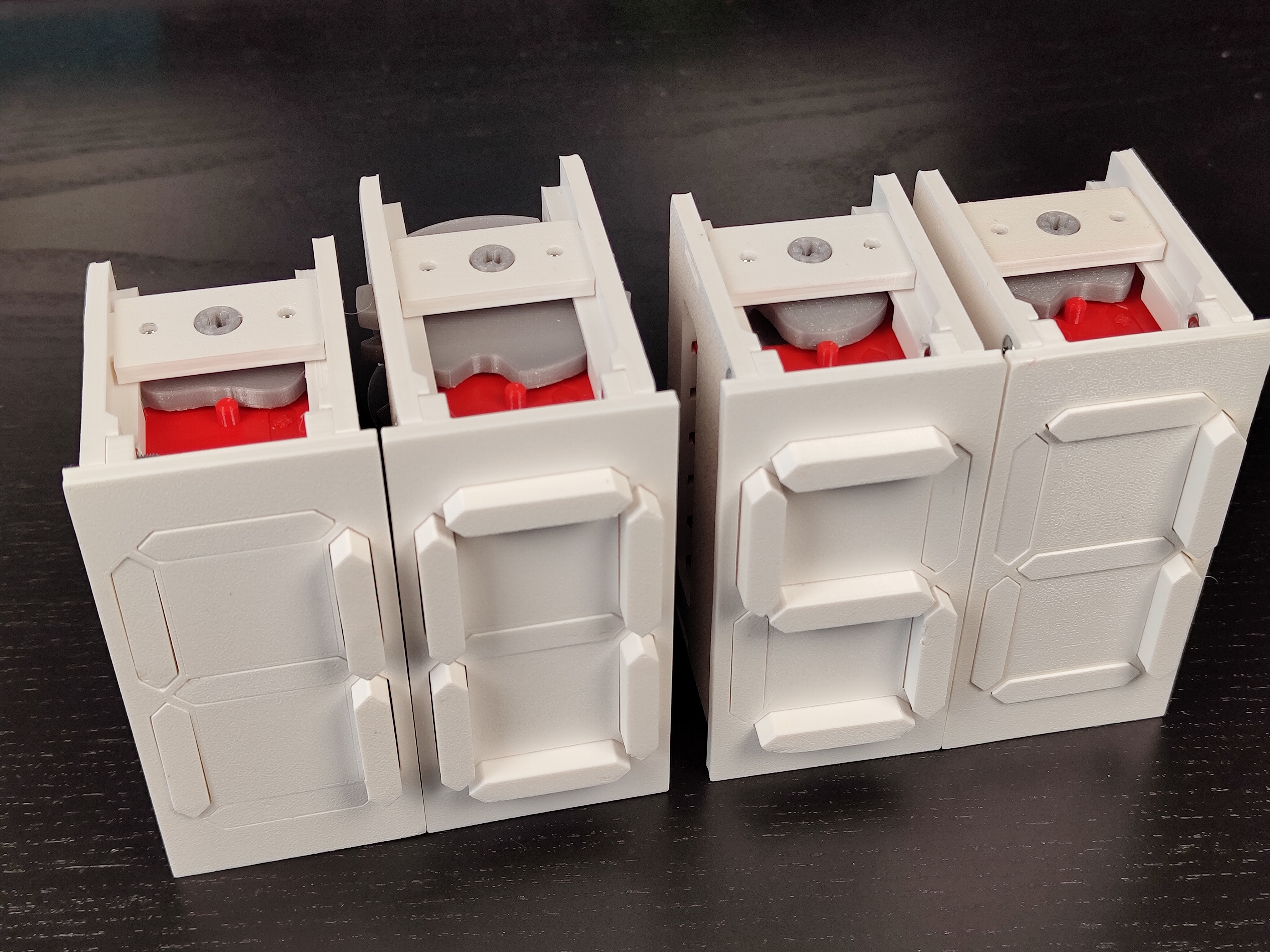
In addition to the files in this model, you need to print four mechanical seven segment displays. From left to right, the digits are:
- Seven Segment Display with the
cam_0-2_CW.stlcamshaft - Large 24h Seven Segment Display with the
cam_0-23_CCW.stlcamshaft - Seven Segment Display with the
cam_0-5_CW.stlcamshaft - Seven Segment Display with the
cam_0-9_CCW.stlcamshaft
Motorization and electronics
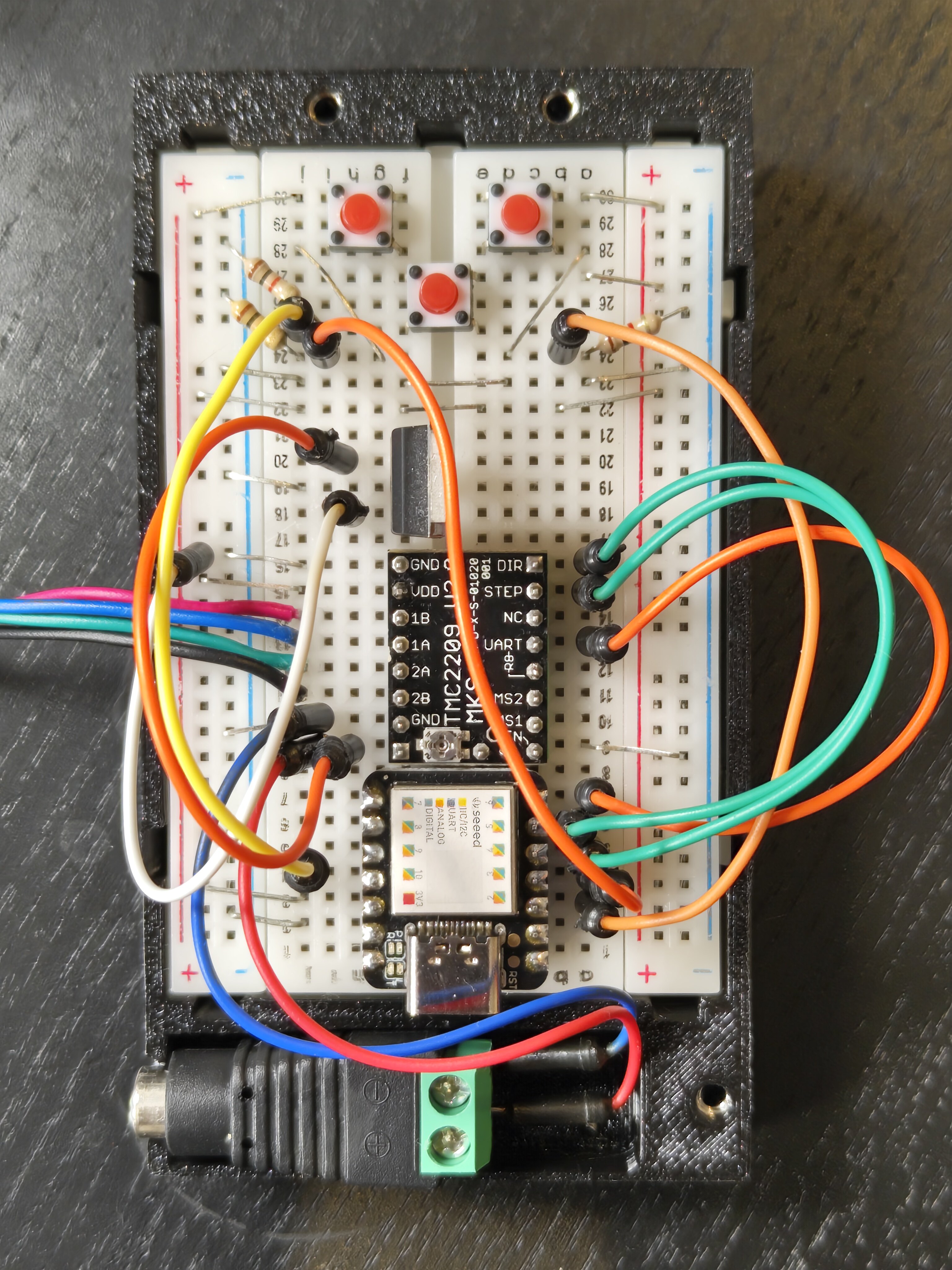
The electronics setup for the motorization will depend on which particular parts you want to use. I provide some information about my setup for reference but this is not a comprehensive tutorial. The motor mount part fits a Nema 17 stepper motor and the electronics enclosure fits a 400-point breadboard. These are the parts I used:
- Seeduino XIAO
- Nema 17 Bipolar 1A 13Ncm 42 x 20mm Stepper Motor
- TMC2209 Stepper Motor Driver
- 12V 2A Power Supply with a 5.5 x 2.5mm DC Plug
- LF50CV voltage regulator to power the Arduino
- push buttons and pull down resistors
Assembly
- Attach two dots to the separator with glue. Insert four square nuts and glue them in place.
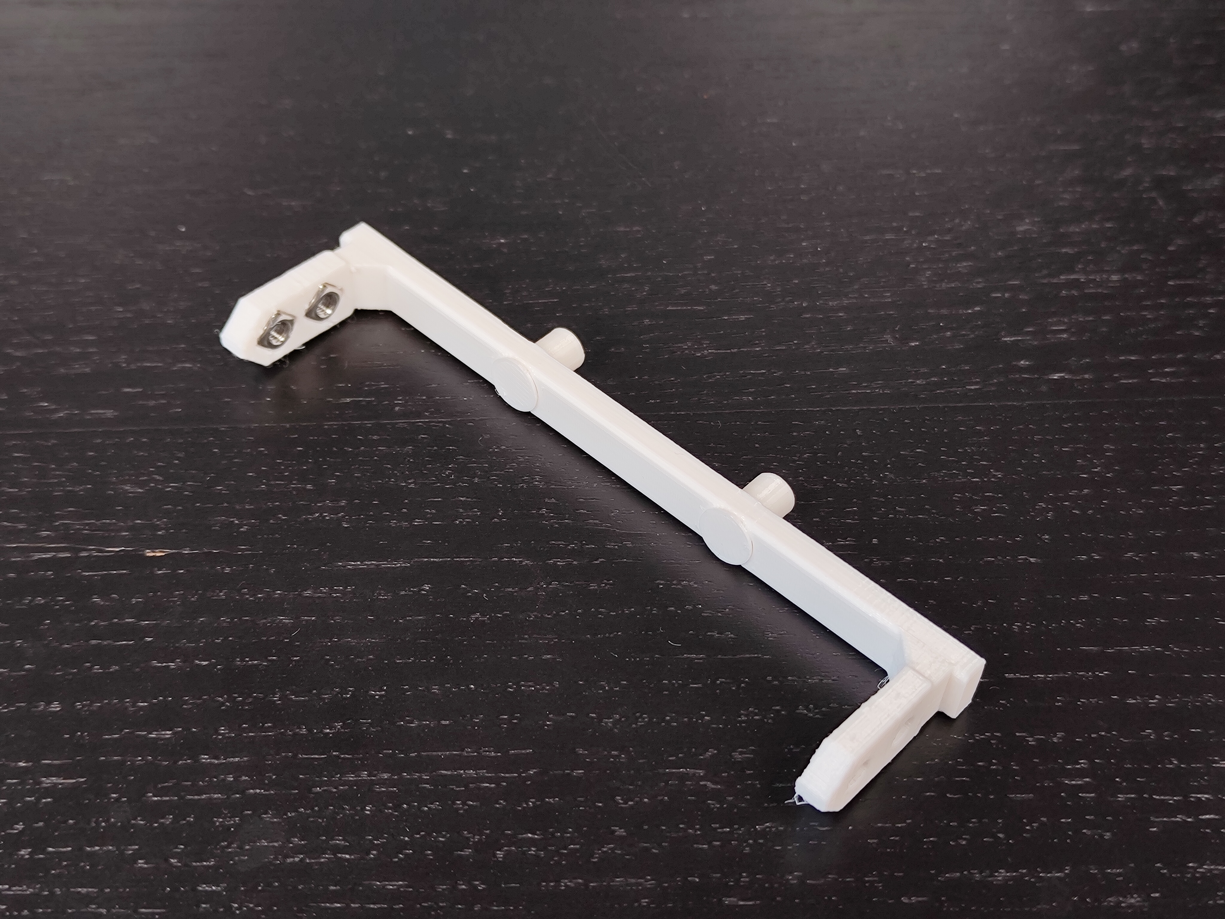
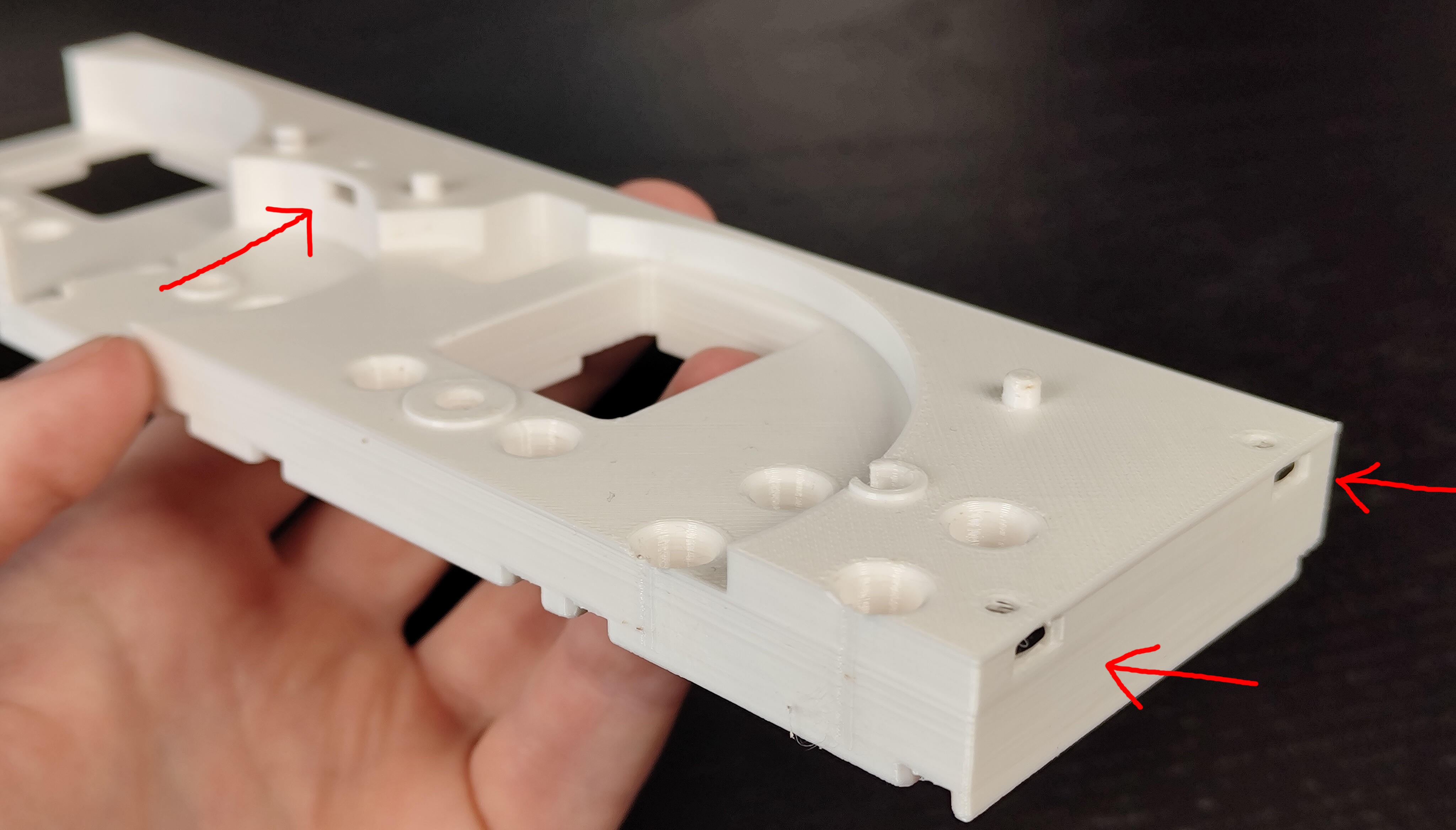
- Insert 3 square nuts into the gearbox
- Place the four digits next to each other
- Put the gearbox on top of the digits and insert 8 screws
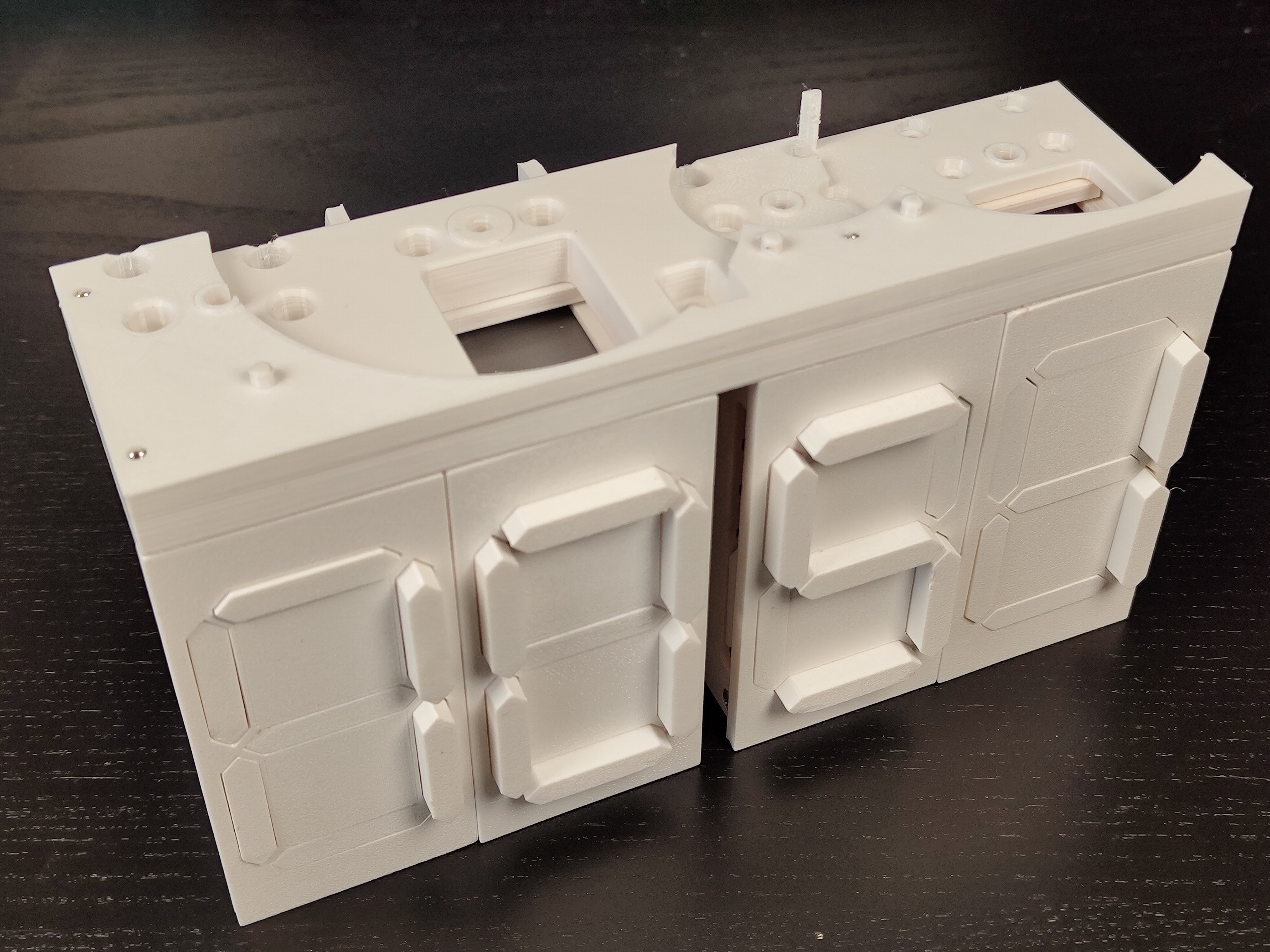
- Place the separator between the digits and attach it with 2 screws
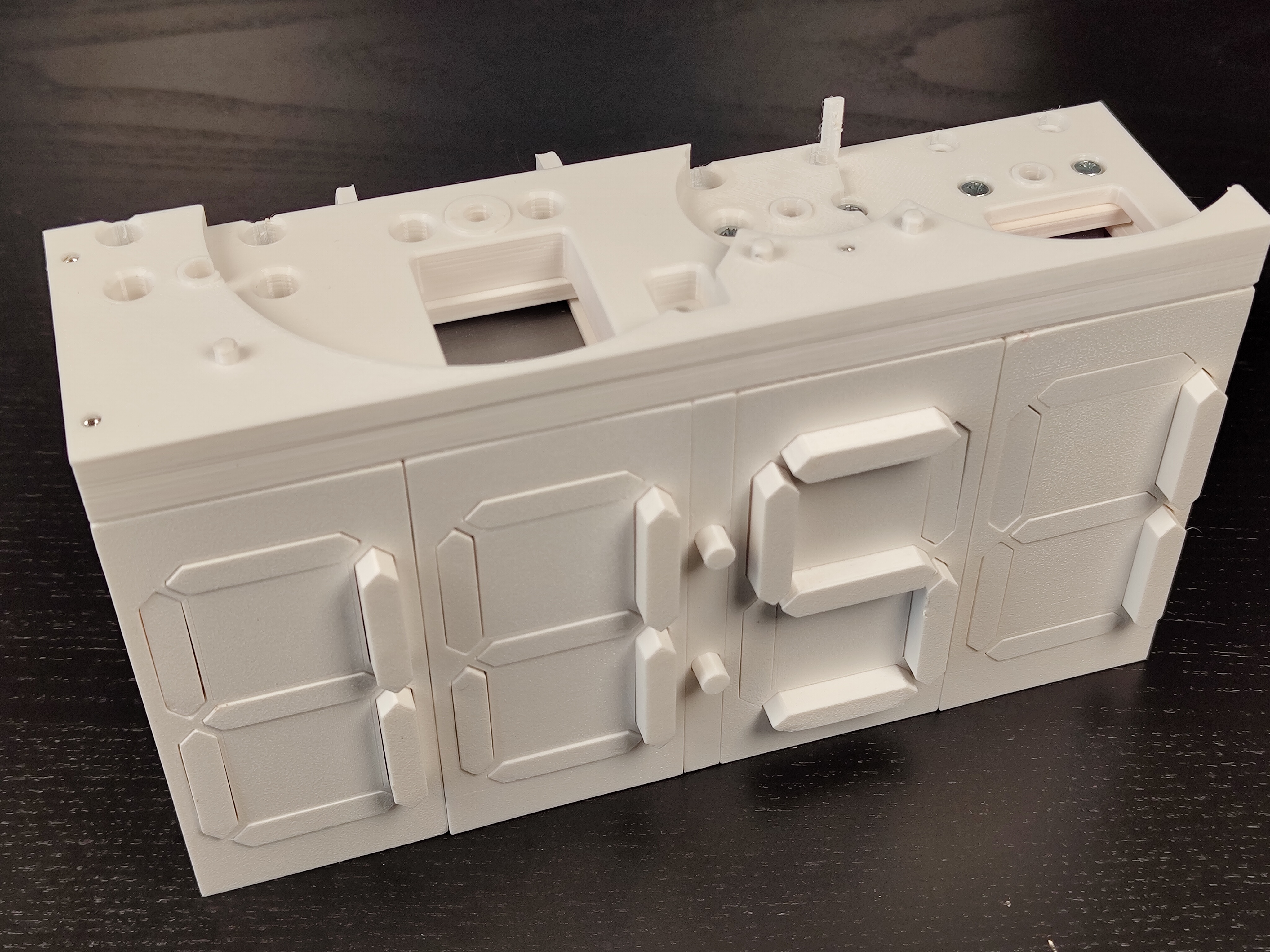
- Turn the assembly upside down and attach the bottom cover with 10 screws
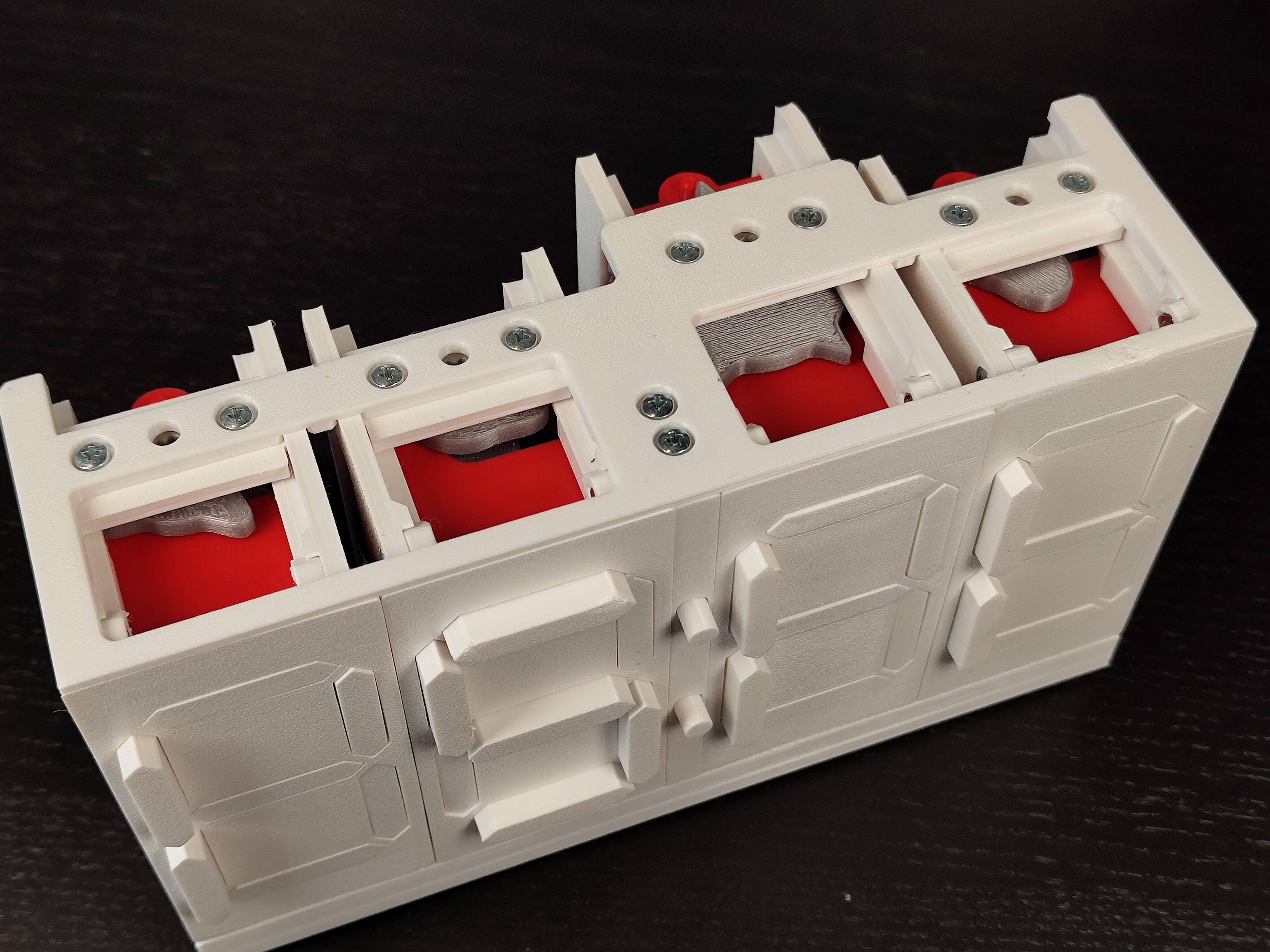
- Insert 2 square nuts into the motor mount
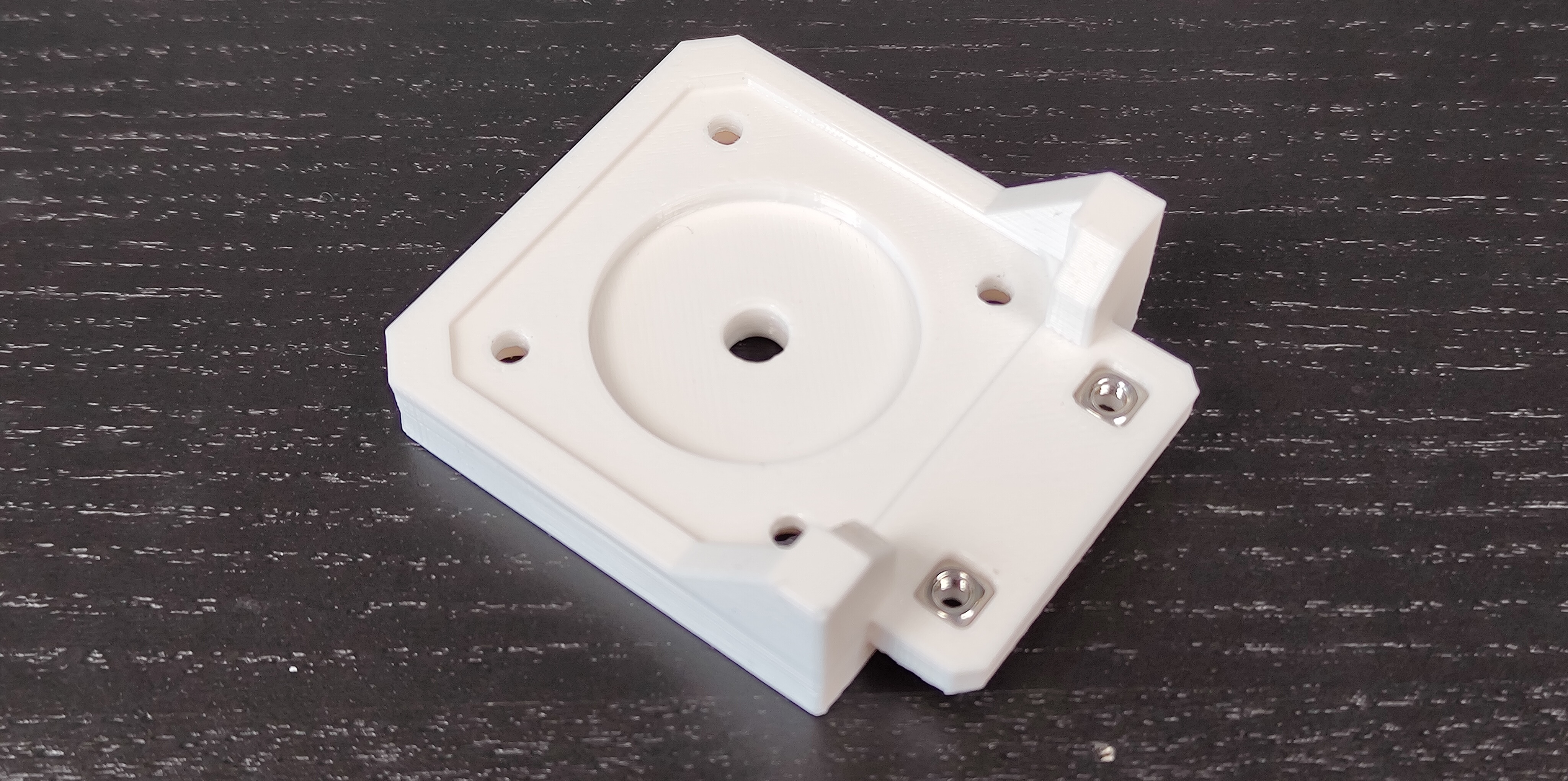
- Attach the motor to the motor mount with 4 screws
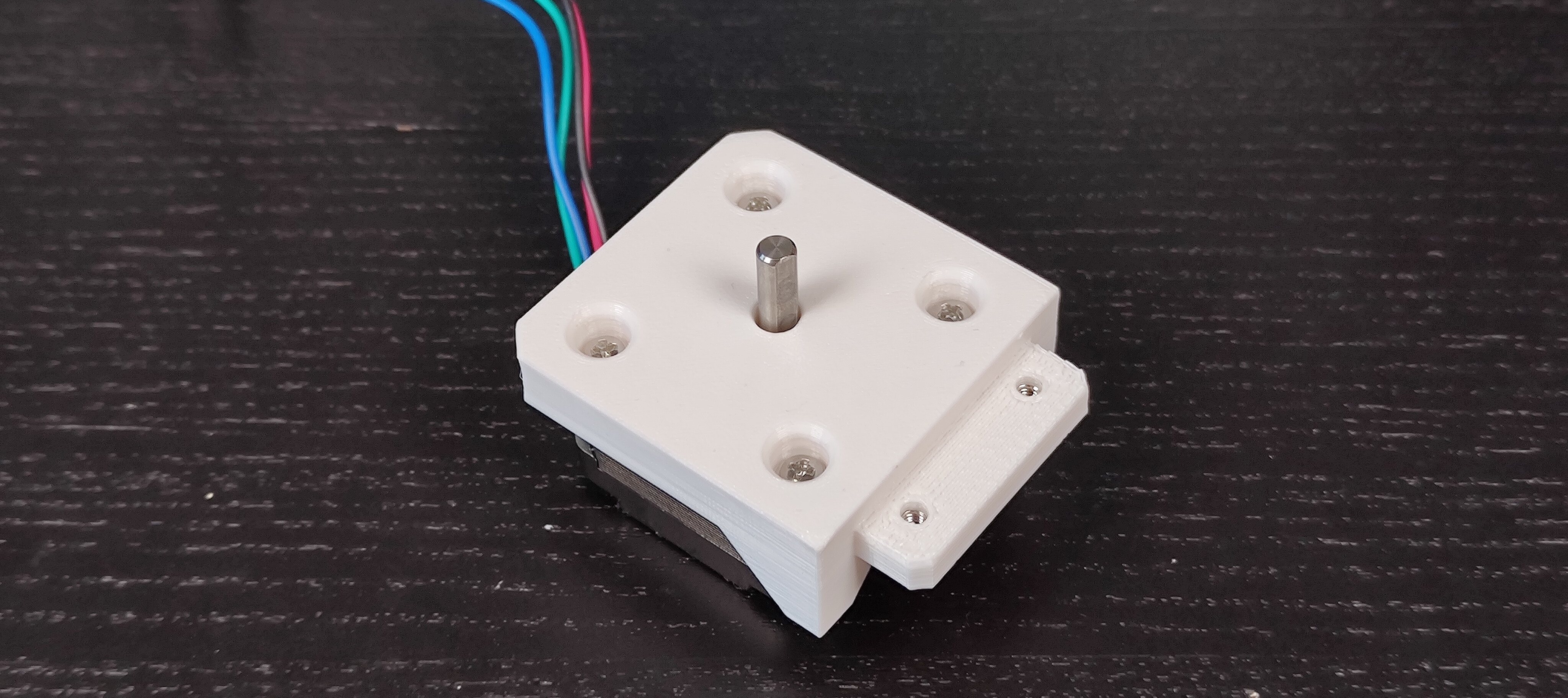
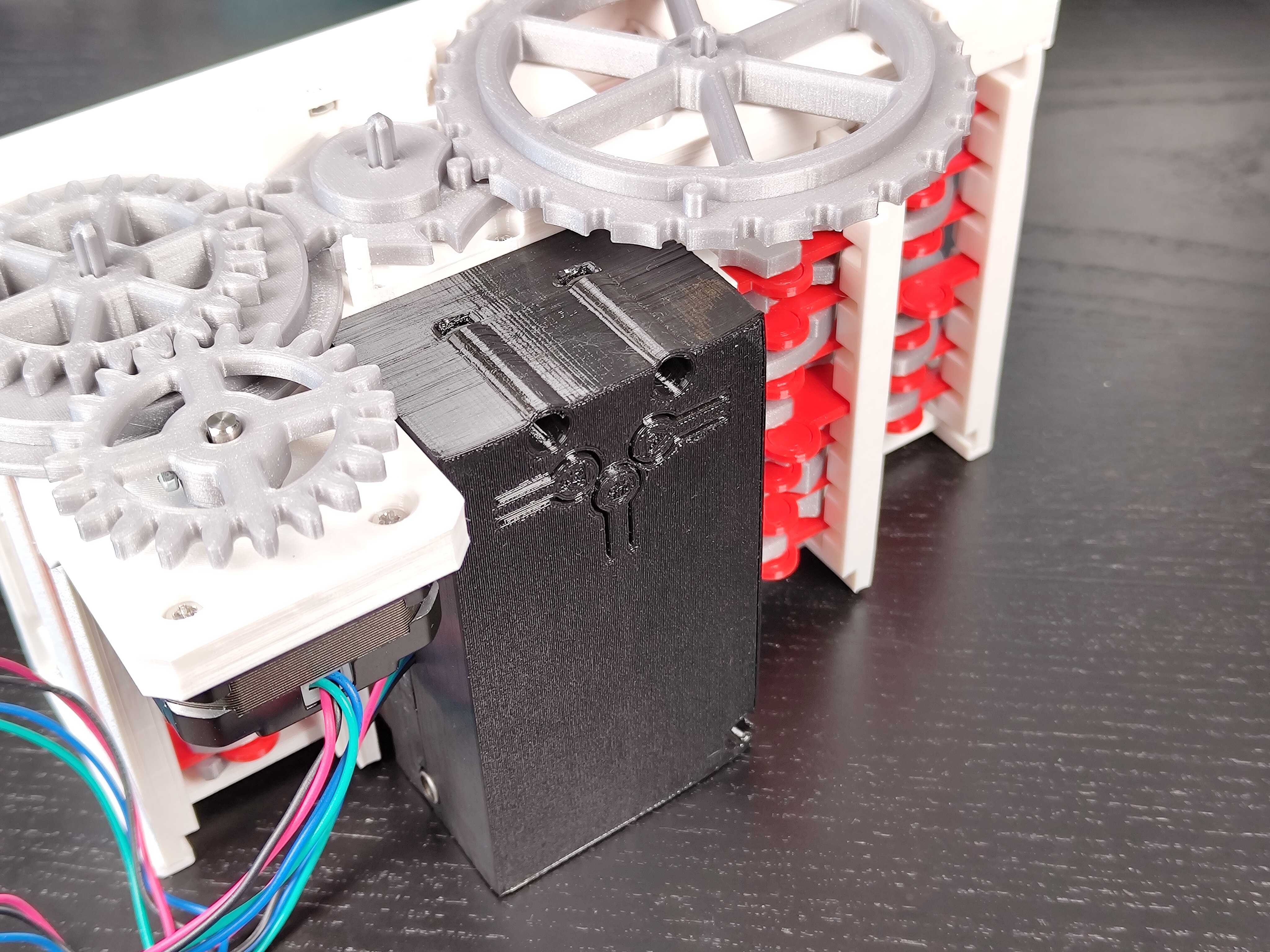
- Attach the motor mount to the gearbox with 2 screws
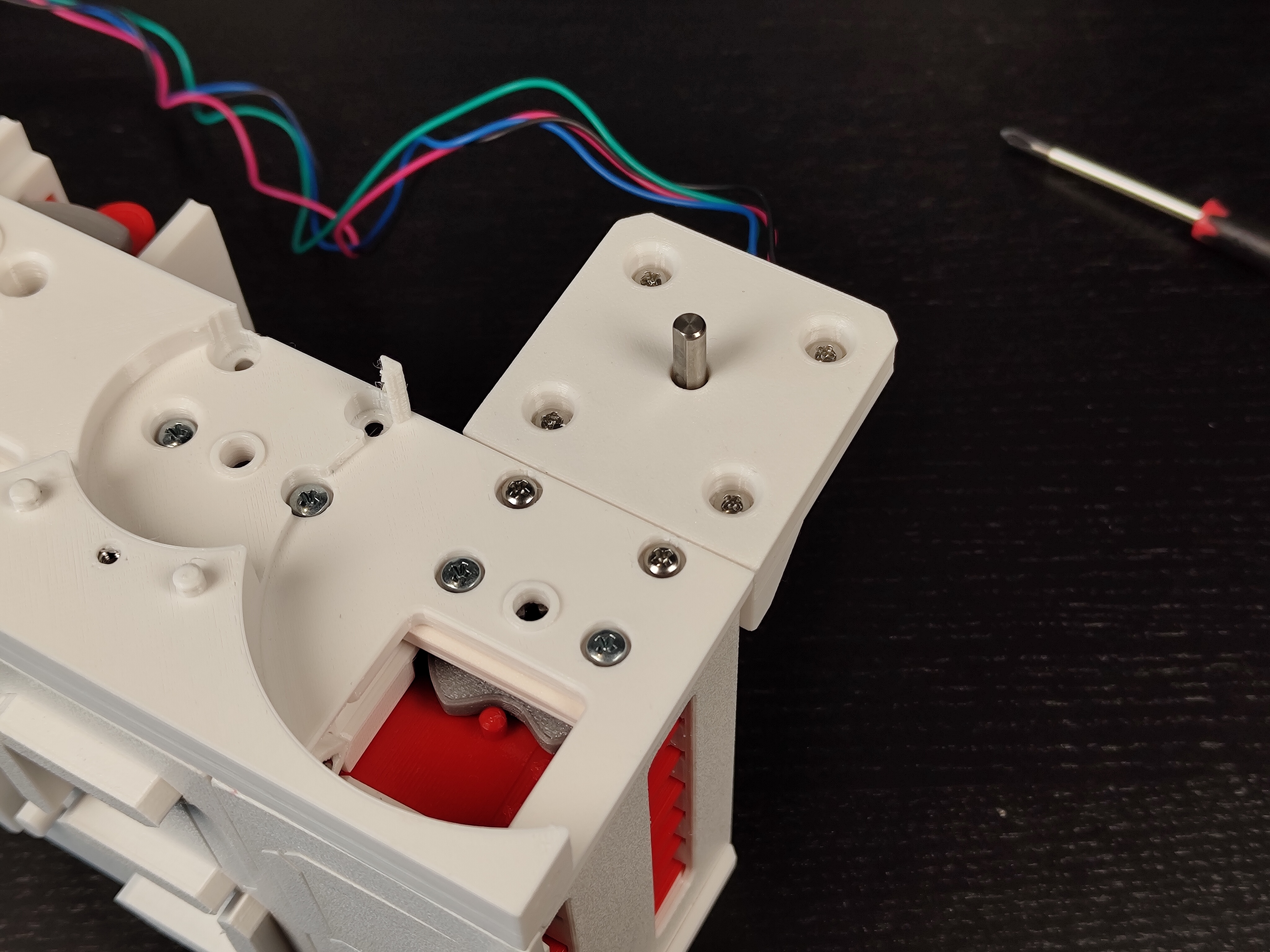
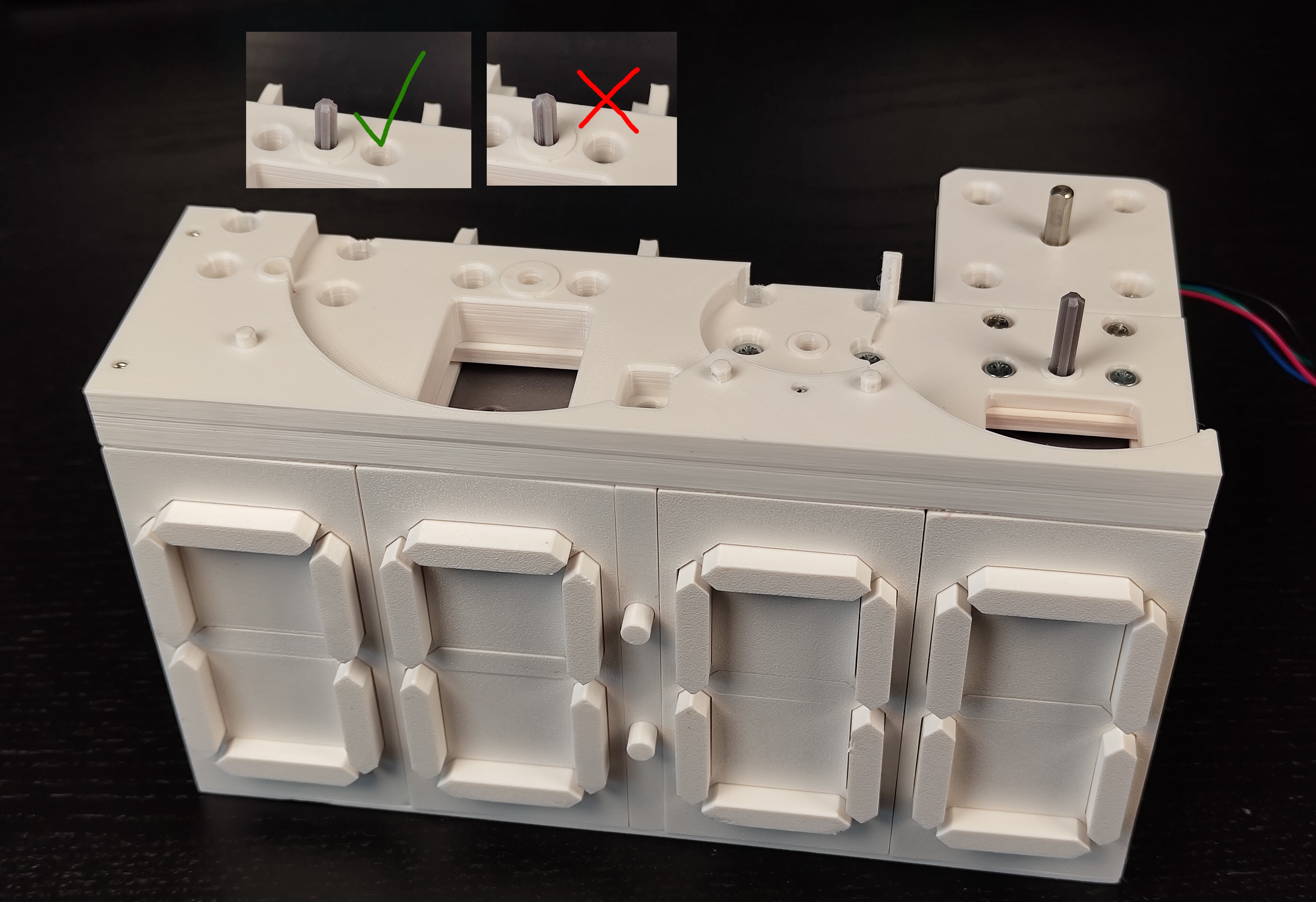
- Use an axle to turn all four digits to 0. The second display has 3 different zeros, you need the one that comes after a 3.
- Put down the four gears and make sure that the alignment line points to the front
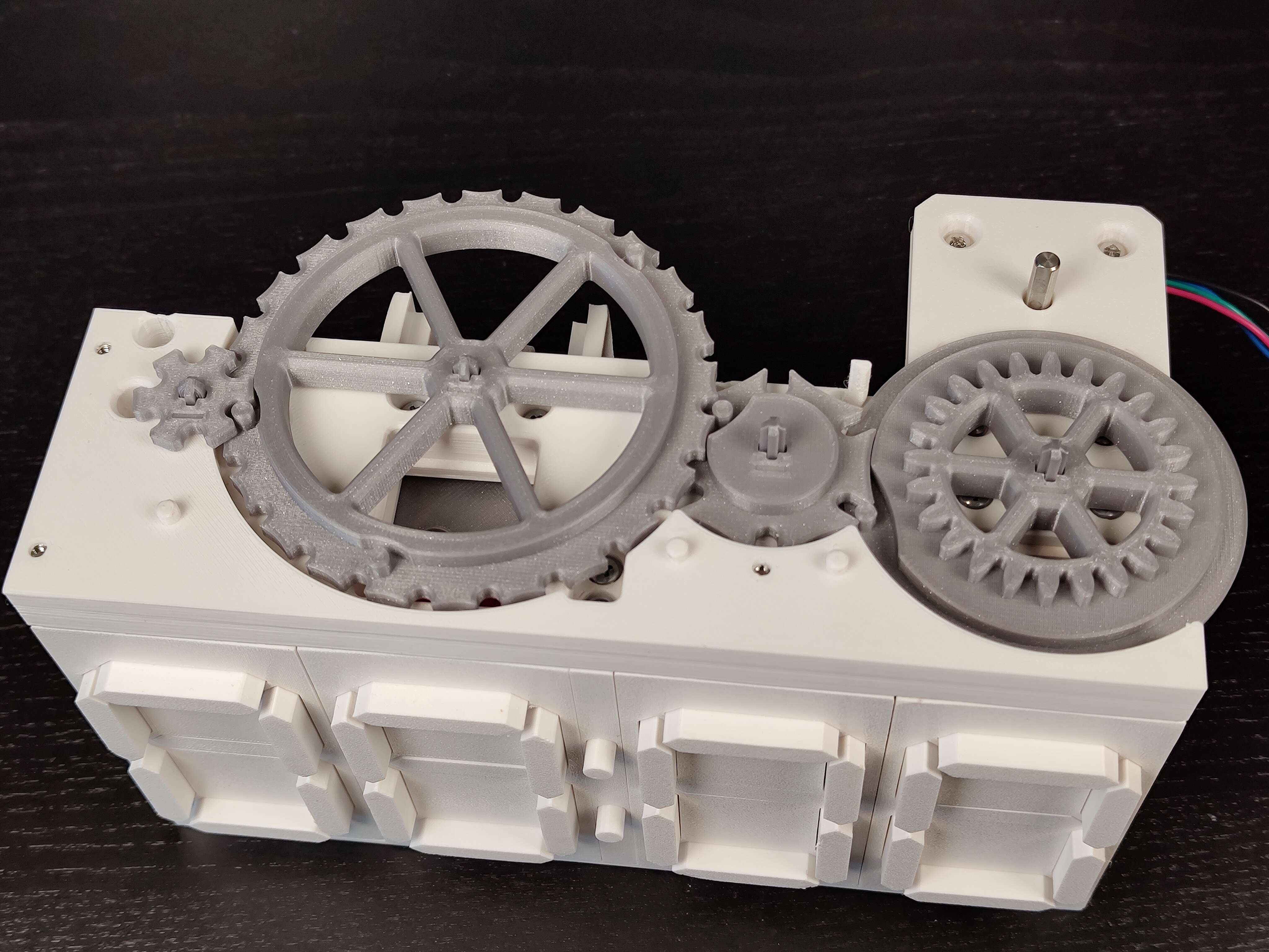
- Place an axle into each gear
- Insert a square nut and a screw into the motor gear, but don't tighten the screw
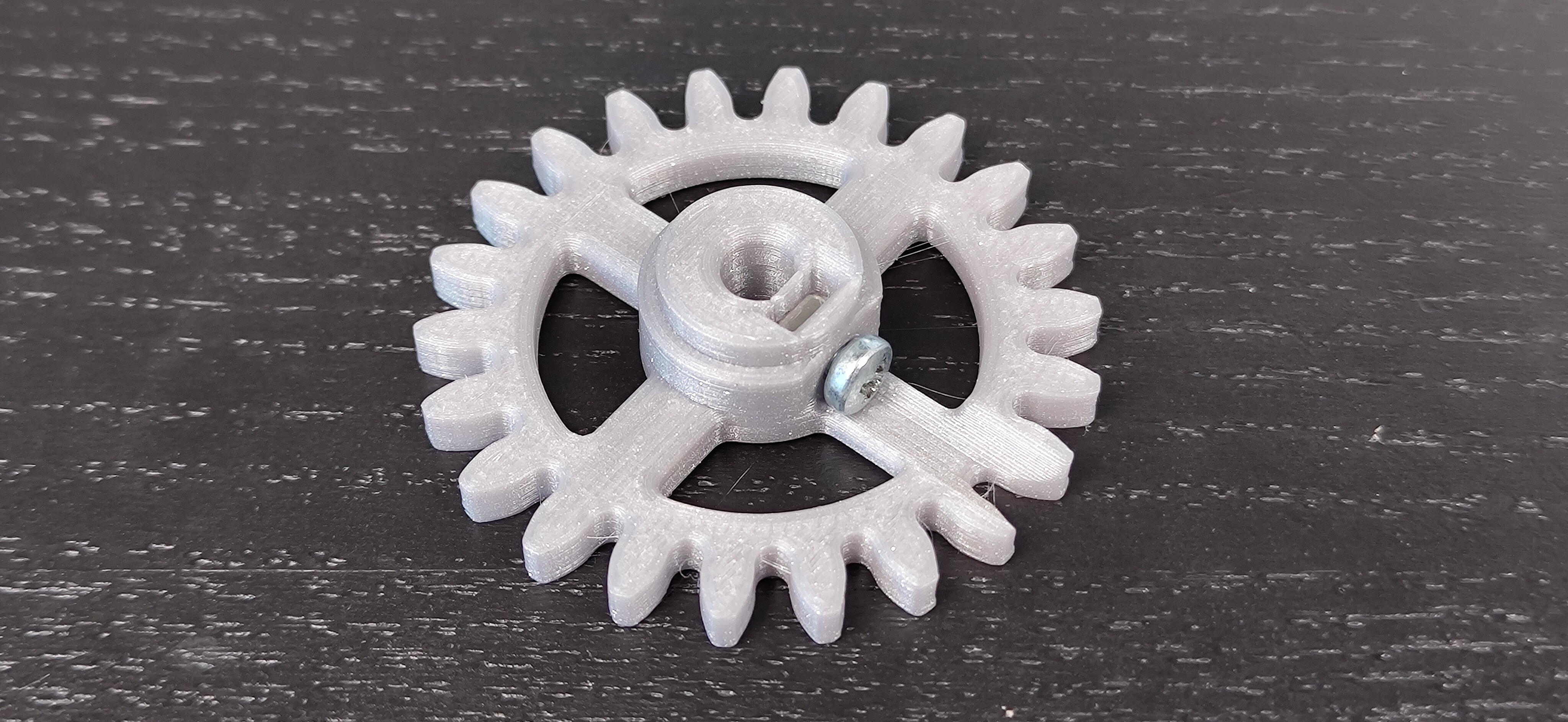
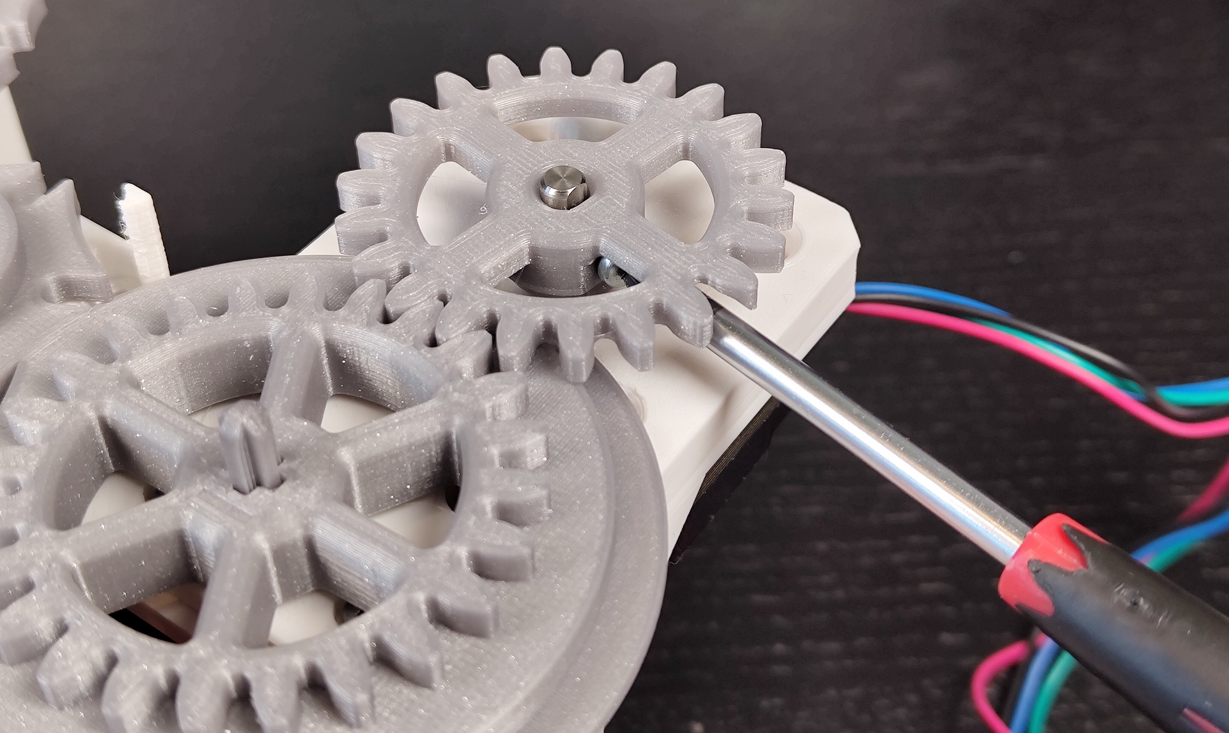
- Attach the motor gear and tighten the screw
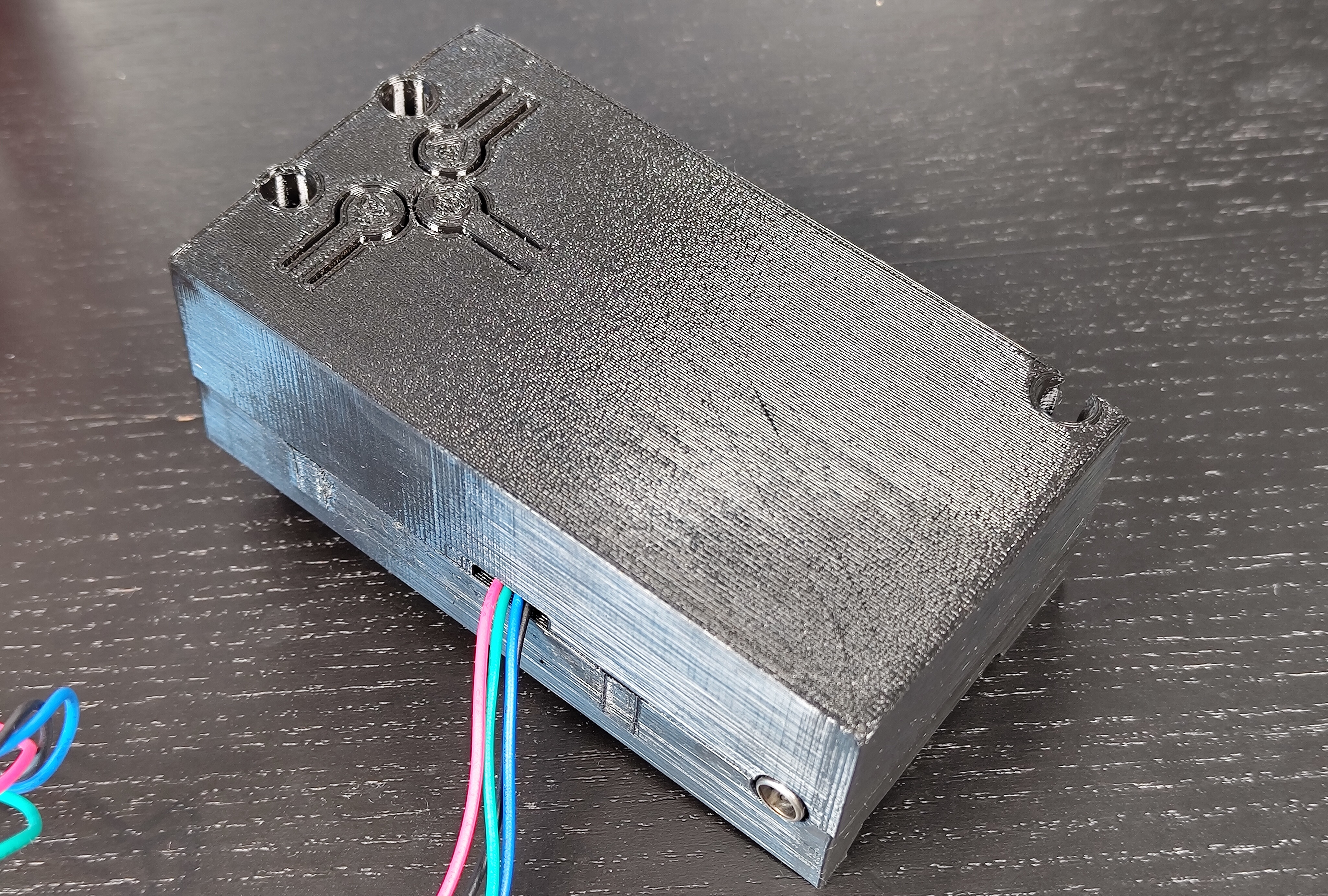
- Optional: Electronics box
- Insert 5 square nuts into the bottom part of the electronics box
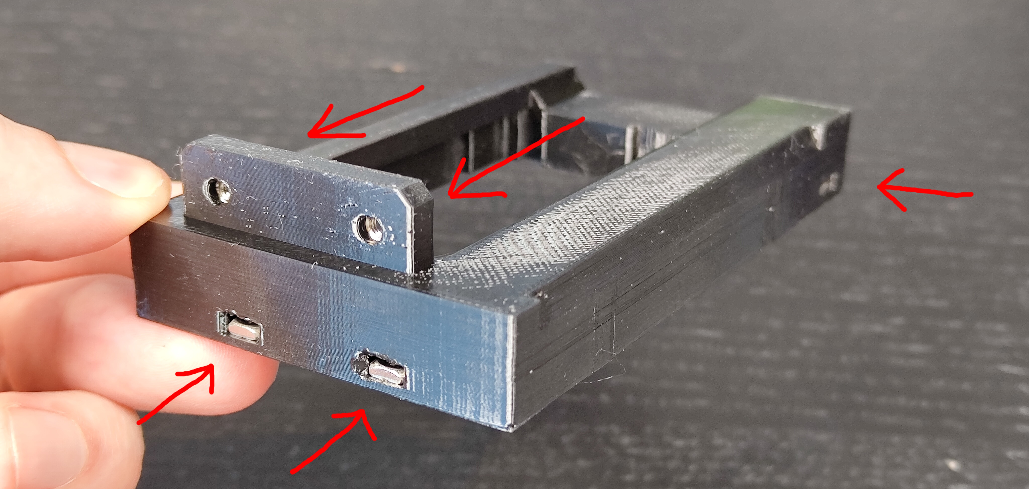
- Place a breadboard with all your components into the box
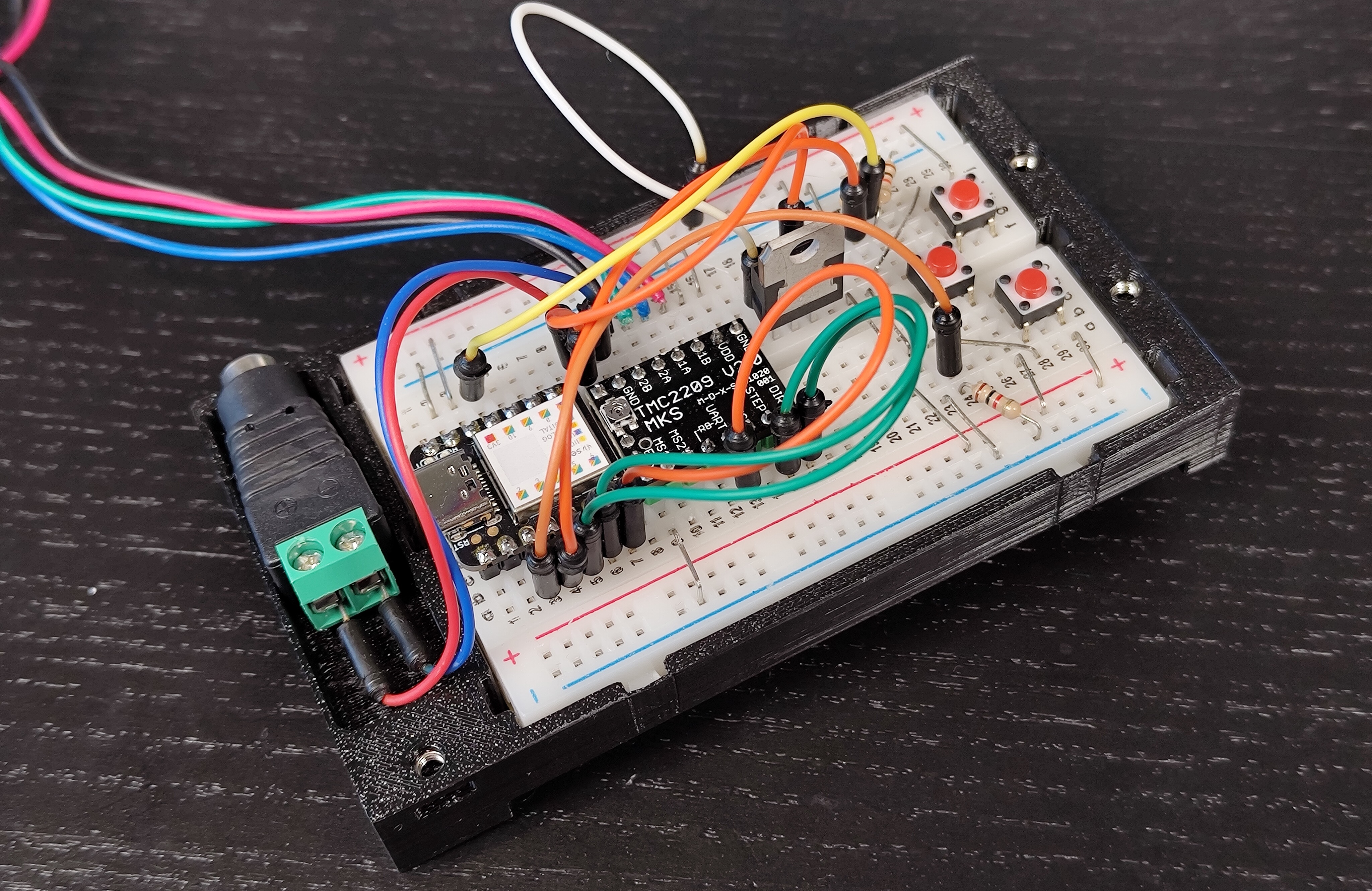 Here is another photo for wiring details:
- Attach the top cover with 3 screws
- Push it into the main assembly and attach it with 2 screws
- Insert 5 square nuts into the bottom part of the electronics box
- Put the top cover on the gearbox and fasten it with 3 screws