
Fine Structured Surface Test Models
We calculate the final price from your selected file. You review and accept it before payment.
Saved on this device.
Model information
- Source
- Printables
- Category
- Test Models
- License
- Creative Commons — Attribution — Share Alike
I was experimenting with changing the geometry of models to create surface structures, which distract from the layered look of standard FDM parts, while in contrast to fuzzy skin, retaining a technical appearance. Depending on the chosen pattern this easily overwhelms my desktop PC so a slicer implementation would likely be the best option in the long run. It seems to work surprisingly well even on high slope angles (positive and negative).
For reference: Model is a 90° arc with inner radius of 50mm a thickness of 10mm and a width of 20mm. Layer
Structures were created in two ways:
Either: Rectangular blind holes were cut into the model with heigths and z-coordinates according to the layer heigth and depths inceasing with slope angle (width 0.1mm, height = layerheight = 0.2mm, depth = 0.5 ... 3mm (approximatly))
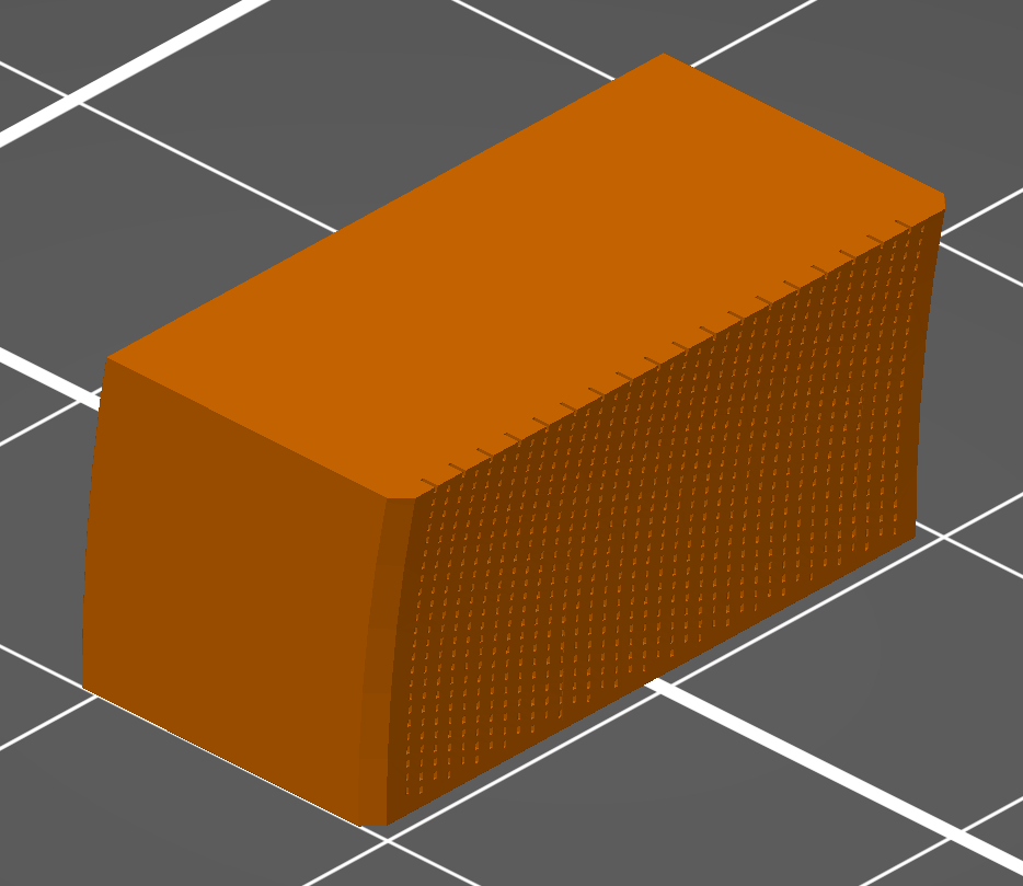
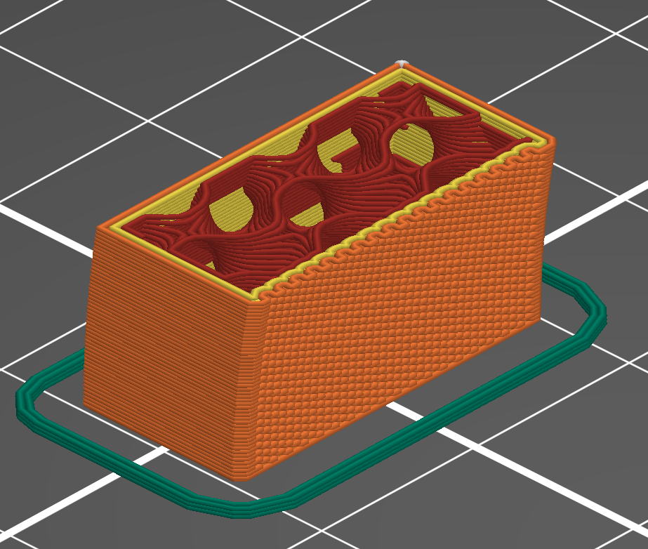
Or: Parrallel cuts with an constant angle to the xy-plane and constant depth were cut into the model. (Angles: 5°, 10° and 20° were tried. Distances of 0.5mm 0.75mm or 1mm seam to work quite good. A cut width of 0.1mm is fine on larger angles, but should be reduced when lowering the angle to keep a constant gap width. A constant cut depth of 0.5mm was used.) The structure is then created as an moiré pattern between the lines and the layer heigth.
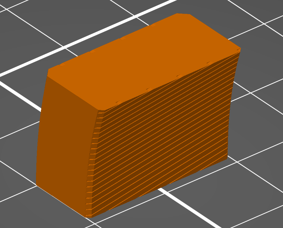
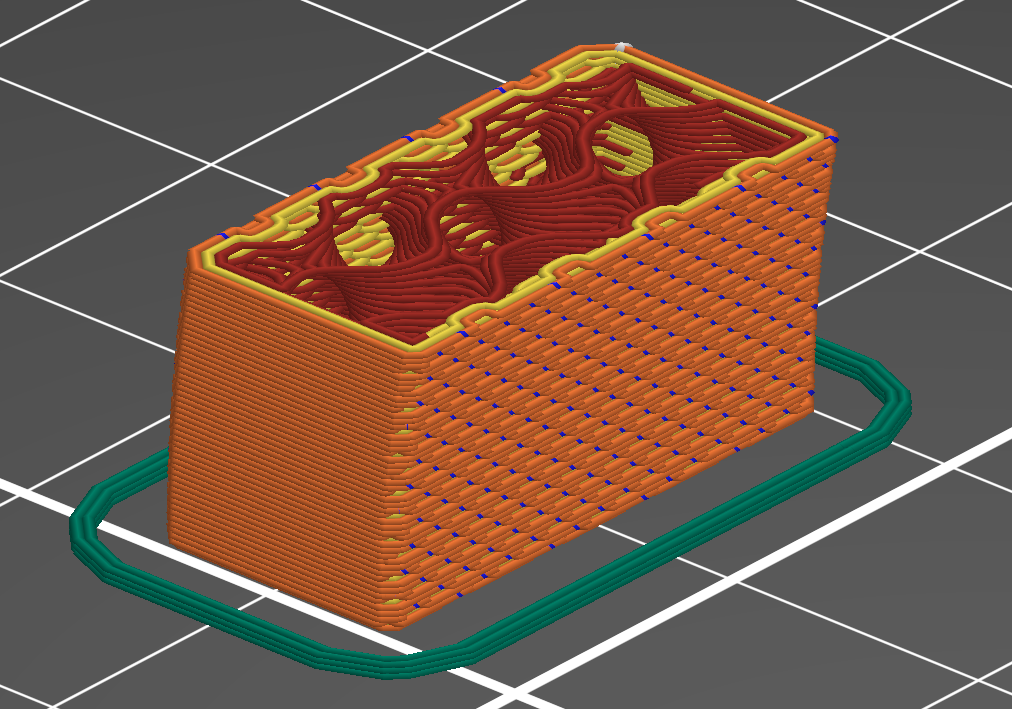
The cylindrical model is created using a rotationally patterned helical sweep cut. It demostrated the capability to completly hide the z-seam with the used ca. 5° angle 0.1mm linewidth and 0.5mm distance. Seam position was set to nearest.
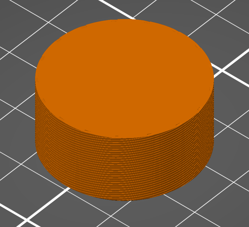
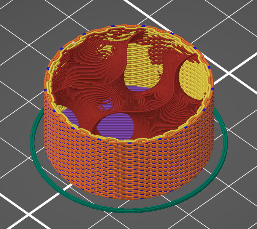
The spherical model was created by a linear extrude cut.