
TMT - Toddler Mobility Trainer
We calculate the final price from your selected file. You review and accept it before payment.
Saved on this device.

An affordable mobility trainer for toddlers who lack the physical strength or coordination needed to move independently.
- Rating
- 0 / 5
- Likes
- 11
- Downloads
- 32
- Makes
- 0
- Views
- 456
- Reviews
- 0
Updated at source:
Model information
- Source
- Printables
- Category
- Other House Equipment
- License
- Creative Commons — Public Domain
Credits:
This product has been developed with the help of Go Baby Go Israel, Shenkar College students, TOM Israel Summer 2022 Interns, and the TOM Global R&D Team. Special thanks to Yara Hijaze from the Hasoub community for translating this document to make it even more accessible!
Applications and Impact:
The Toddler Mobility Trainer - Size Small - Rev 2.0 assists children aged 6 months to 3 years old who have difficulty moving independently. It provides a cost-effective solution for enhancing mobility in indoor environments, promoting independence and physical activity.
Project Details:
- Estimated Manufacturing Time:
- 4 Hours of machine time
- 2 Hours of assembly
- Materials Needed: See BOM
- Technologies Used: CNC Machining, Laser Cutting, Sewing, 3D Printing.
Bill of Materials (BOM):
| Item # | Item Description | Material | Manufacturing Instructions | Dimensions | Quantity | Purchase Link / Supplier |
| Chair Base | ||||||
| 1A | Back support | 9mm Birch plywood | CNC | 120*80cm for all parts | 1 | Harlow shop |
| 1B | Seat | 1 | ||||
| 1C | Base | 1 | ||||
| 1D | Heel support | 1 | ||||
| 1E | Footrest | 1 | ||||
| 1F | Right side | 1 | ||||
| 1G | Left side | 1 | ||||
| 2 | M4 wood screw | Steel | Off the shelf | M4x20mm | 25 | Amazon link |
| Straps | ||||||
| 3 | Waist Strap | Nylon | Off the shelf | 50*1100mm | 2 | Amazon link |
| 4 | Waist strap loop | Nylon | Sewing | 50*200mm | 1 | Amazon link |
| 5 | Waist strap hook | Nylon | Sewing | 50*200mm | 1 | |
| 6 | M6 barrel nuts | Steel | Off the shelf | Inner diameter: 6mm External diameter: 8mm Cylinder length: 8mm | 6 | Amazon Link |
| 7 | M6 screws | Steel | Off the shelf | Length: 8mm | 6 | McMaster link |
| 8 | M6 washer | Steel | Off the shelf | 4 | Amazon link | |
| 9 | Foot strap | Nylon | Scissors + sewing machine | 25*400mm | 2 | Amazon link |
| 10 | Foot strap hook | Nylon | Laser cutting + sewing machine | 25*120mm | 2 | Amazon link |
| 11 | Foot strap loop | Nylon | Laser cutting + sewing machine | 2 | ||
| Wheels | ||||||
| 12 | Front wheel | Polyurethane PU Rubber | Off the shelf | Swivel castor Mount height: 35mm Diameter: 25mm | 2 | Amazon Link |
| 13 | Back wheel | Polyurethane | Off the shelf | Mount height:126mm Diameter: 100mm | 1 | Mcmaster Link |
| 14 | M4 screw inserts | Stainless Steel | Off the shelf | Inner diameter: 4mm External diameter: 8mm Cylinder length: 8mm | 8 | Amazon Link |
| 15 | M4 screws | Steel | Off the shelf | Length: 8mm | 8 | McMaster link |
| *6 | M6 barrel nuts | Steel | Off the shelf | *included in rows 6-7 | Amazon Link | |
| *7 | M6 screws | Steel | Off the shelf | McMaster link | ||
| 16 | Side wheel | Polyurethane | Off the shelf | Diameter: 300mm | 2 | Amazon Link (linked set comes with axle, washers + nuts) |
| 17 | Axle screw | Steel | Off the shelf | Diameter: 12mm | 2 | |
| 18 | M12 washer | Steel | Off the shelf | Diameter: 23mm | 4 | |
| 19 | M12 nut | Steel | Off the shelf | 2 | ||
| 20 | M12 Nyloc nut | Steel | Off the shelf | 2 | Amazon link | |
| 21 | Side wheel cover | PETG | 3D Printing | 80 Grams | 10 | Link |
| Cushions | ||||||
| 22 | Back foam | Polyurethane Foam | Laser cut | 552*277mm | 1 | Amazon Link |
| 23 | Seat foam | Polyurethane Foam | Laser cut | 240*208mm | 1 | |
| Back Cushion Cover | ||||||
| 24 | Back fabric | Poly Poplin Polyester Fabric | Laser cut + Sewing | 564*288mm | 1 | Amazon Link |
| 25 | Front fabric | Poly Poplin Polyester Fabric | Laser cut + Sewing | 564*328mm | 1 | |
| 26 | Belt loops fabric | Poly Poplin Polyester Fabric | Laser cut + Sewing | 27*60mm | 4 | |
| 27 | Back connection fabric | Poly Poplin Polyester Fabric | Laser cut + Sewing | 27*720mm | 1 | |
| 28 | Back fabric hook | Nylon - Hook | Off the shelf + sewing | 25*280mm | 1 | Amazon link |
| 29 | Front fabric loop | Nylon - Loop | Off the shelf + sewing | 25*280mm | 1 | |
| 30 | Double sided Hook-Loop | Nylon - Double sided | Off the shelf + sewing | 25*100mm | 2 | Amazon link |
| Seat Cushion Cover | ||||||
| 31 | Bottom fabric | Poly Poplin Polyester Fabric | Laser cut + Sewing | 250*218mm | 1 | Amazon link |
| 32 | Top fabric | Poly Poplin Polyester Fabric | Laser cut | 250*258mm | 1 | |
| 33 | Seat connection fabric | Poly Poplin Polyester Fabric | Laser cut | 27*250mm | 1 | |
| 34 | Bottom fabric hook | Nylon - Hook | Off the shelf + sewing | 25*140mm | 1 | Amazon link |
| 35 | Top fabric hook | Nylon - Loop | 25*140mm | 1 | ||
MAKE THE PARTS
STEP #1 - CNC Wood instructions:
The following files are downloadable from the CNC folder in the download section.
*if you are using an outside CNC vendor, both files should be sent to ensure proper production:
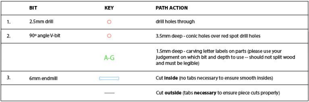
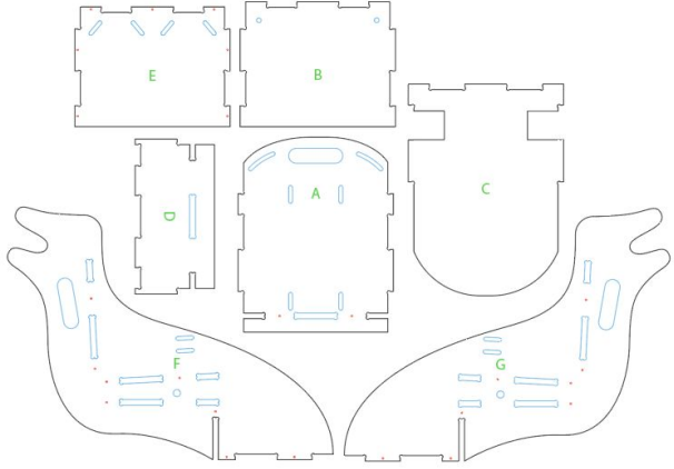
1. TMT 2_AllPartsCNC.dxf - DXF file to be sent to the CNC machine/vendor
2. TMT 2_AllPartsCNC.pdf - (below) contains bit and toolpath information for proper CNC manufacturing.
STEP #2 - Cut All Foam + Fabric Parts
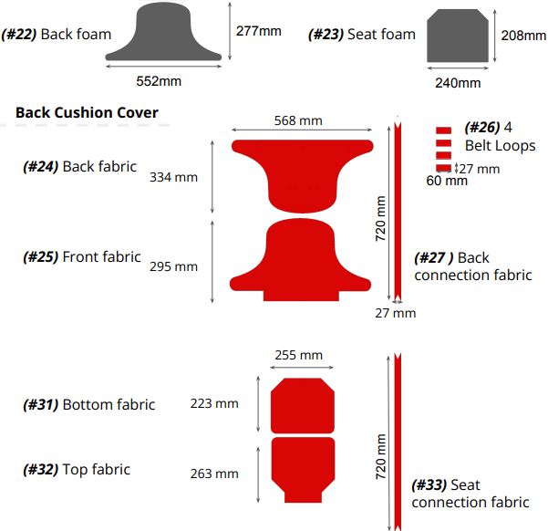
Cut cushion foam (BOM #22-23) and all cushion cover fabrics (#24-27, #31-33).
*Optional - to be more precise, use a laser cutter*
STEP #3 - Prepare All Hook + Loop Pieces
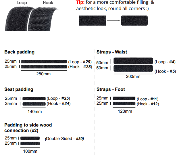
Measure and cut all hook and loop pieces
STEP #4 - Cut straps
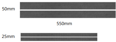
For the waist straps, prepare two 50mm wide, 550mm long waist straps (#3) and two 25mm wide, 400mm long foot straps (#9).
STEP #5 - Print side wheel covers
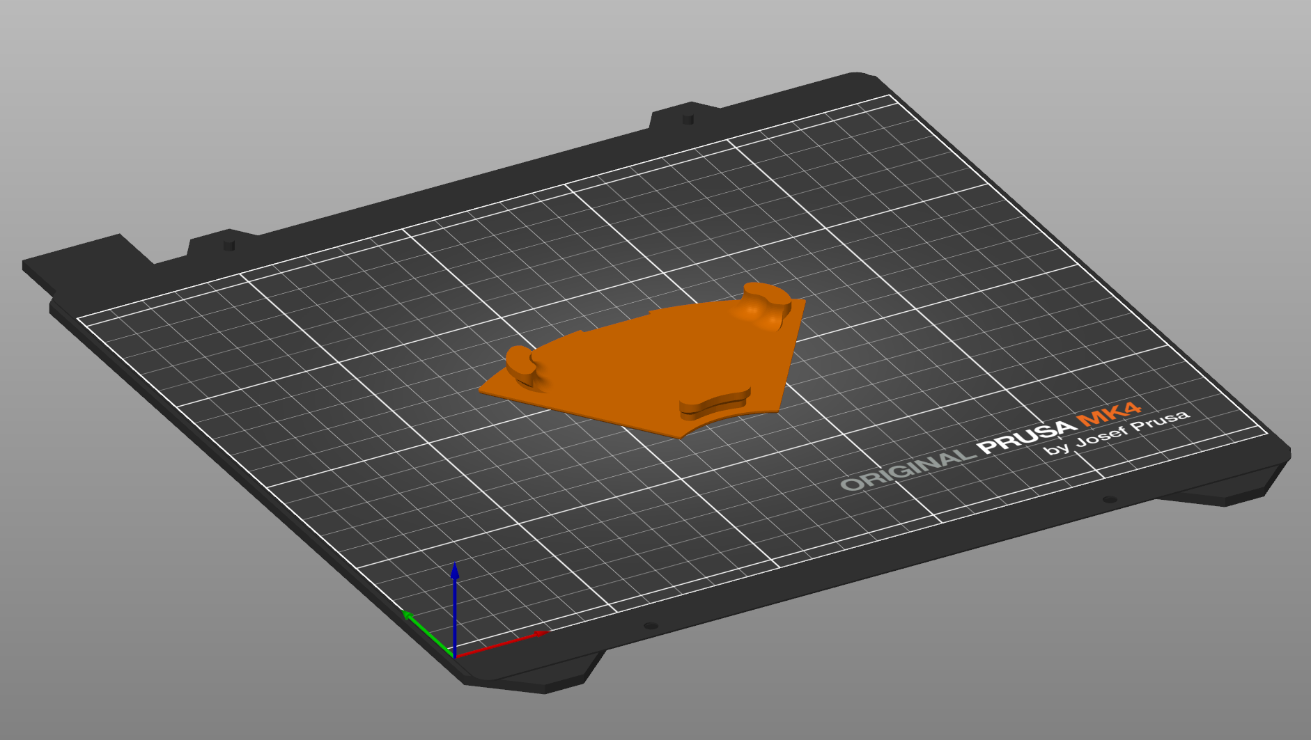
Print 10 Pieces of “Wheelcover V2” from PETG or similar material.
ASSEMBLY GUIDE
STEP #1 - Prepare cushion covers
STEP #1.1
Sew fabric belt loops (#26) onto Back cushion cover - back fabric (BOM #24) - Outside (face with color).
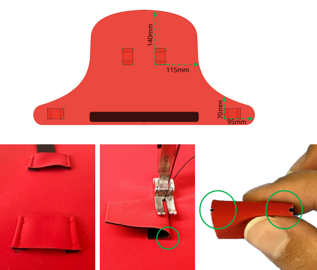
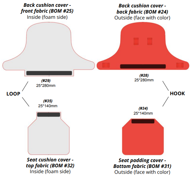
Sew hook and loop pieces to fabric as illustrated:
STEP #1.2
Sew back cushion cover - back fabric and -front fabric parts (BOM #24-25), and seat cushion cover - bottom fabric and -top fabric parts (BOM #24-25) to one another, leaving hook and loop areas free to insert foams.
Sew 5mm offset from the outer shape.
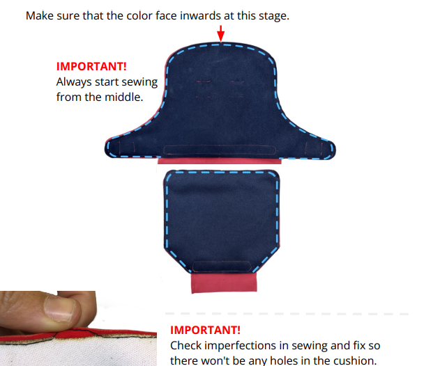
STEP #1.3
Flip covers colored-side-out and insert back and seat foams (#22-#23) into fabric pouches.
Thread back connection fabric (#27) through back fabric belt loops.
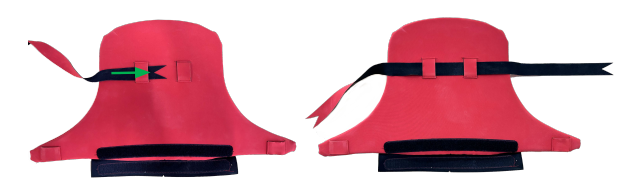
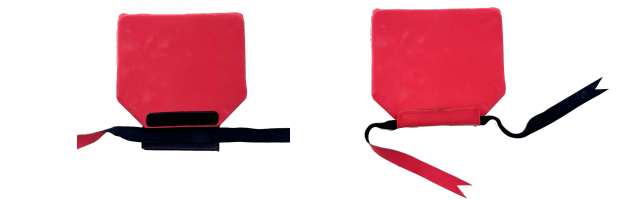
Place seat connection fabric (#33) inside the slit of the seat padding. Close the slits.
STEP #2.1 - Waist Strap
Sew the waist straps with the hook and loop pieces.
Note the difference between the hook and loop straps: → The direction of the double hem on the edge opposite the 75mm grip loops!
Waist strap (#3) - LOOP
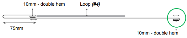
Waist strap (#3) - HOOK

STEP #2.1 - Waist Strap
Make an approximately 8mm ‘plus (+)’ shaped cut 10mm in from the hem and use a lighter to secure edges.
Waist strap - LOOP

Waist strap - HOOK

STEP #2.3 - Prepare Foot Straps
For each foot strap - (#9):
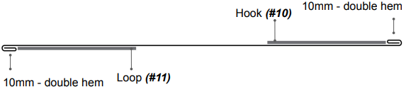
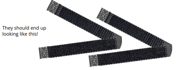
STEP #4 - Prepare All Wood Parts
STEP #4.1 - Sanding
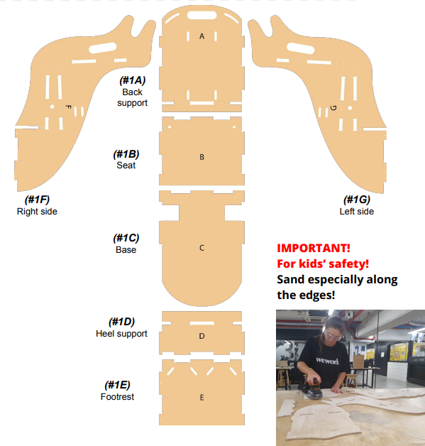
STEP #5 - Attach Waist Secure Straps
Fasten waist straps in place.
1. With the engraving face up: Insert M6 barrel nuts (#6) through holes of the seat (#1B).
2. Flip piece over so engraving is not visible.
3. Place waist strap (#3) flush side down.
4. Place M6 washer (#8) 5. Secure with M6 screw (#7)
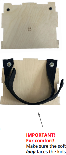
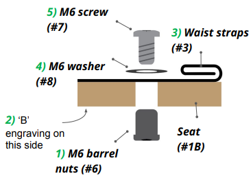
STEP #6 Connecting the wheels
STEP #6.1 - Prepare Front Wheels
Set the footrest (BOM #1E) so all conic holes are facing up. Measure 30mm from side and 10 mm from bottom edges + mark.
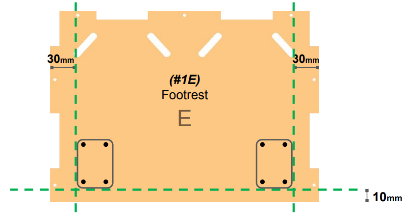
Place small front wheels (#12) at the inside vertices and mark holes, as shown below
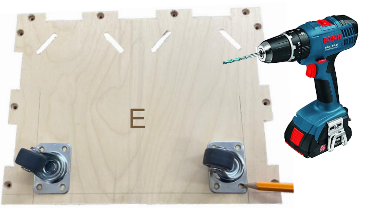
Using a 6mm drill bit, drill through where the wheels will be attached. Sand the wood so that no artifacts remain from the drilling.
STEP #6.2 - Mount Front Wheels
Set the footrest (BOM #1E) so the engraved letter E is facing down.
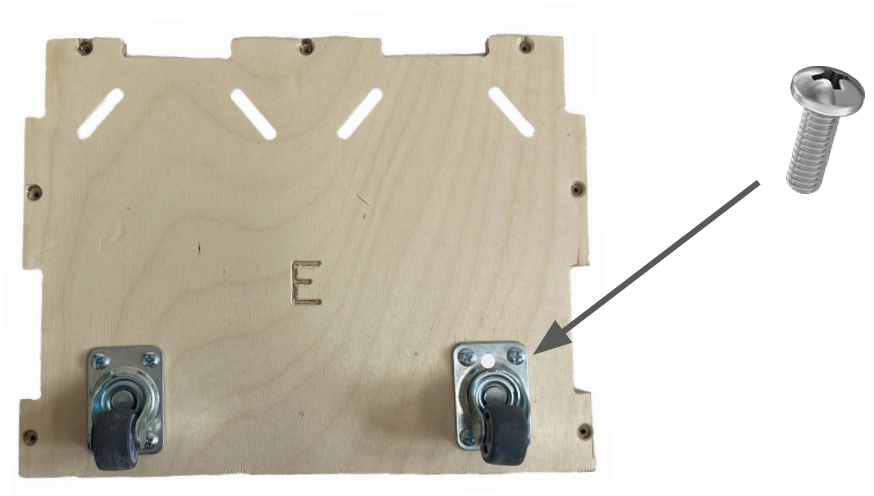
Add M4 screw inserts (#14) into wheel holes.
Tighten with allen key. Ensure insert top is level with wood.
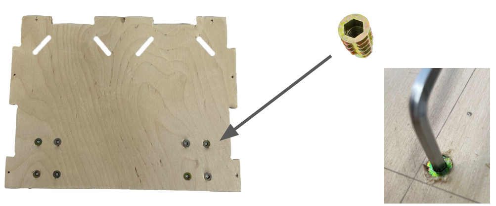
Put small front wheels on holes with inserts. Fasten with 8 M4 screws (#15).
STEP #7 - Prepare Back Wheels
On base (BOM #1C) mark 10mm away from the rounded edge and mark centerline.
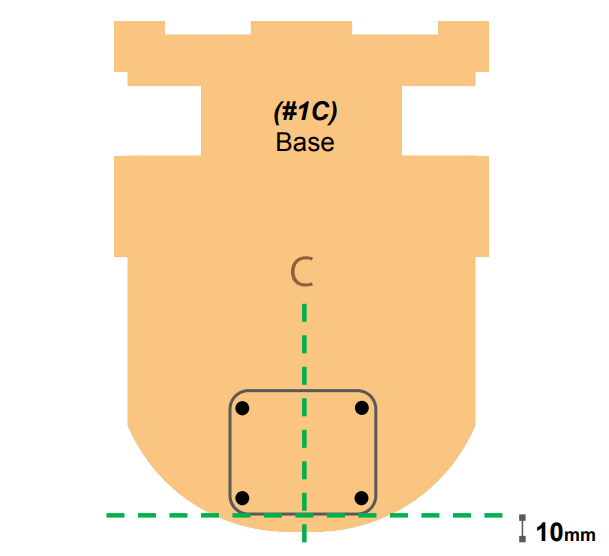
Place back wheel (#1) along the horizontal line and centered atop the vertical line, mark holes, as shown below:
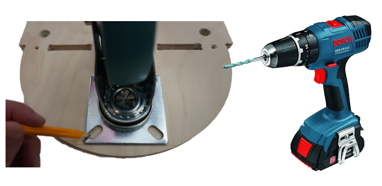
Using a 8mm drill bit, drill holes where the wheel will be attached.
STEP #7.1 - Mount Back Wheel
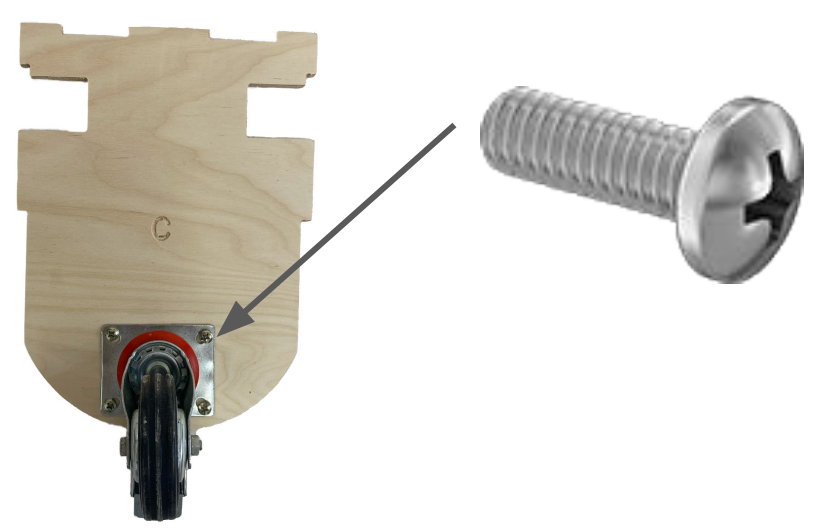
Insert the M6 Barrel Nuts (BOM #6) into the 8mm drilled holes.
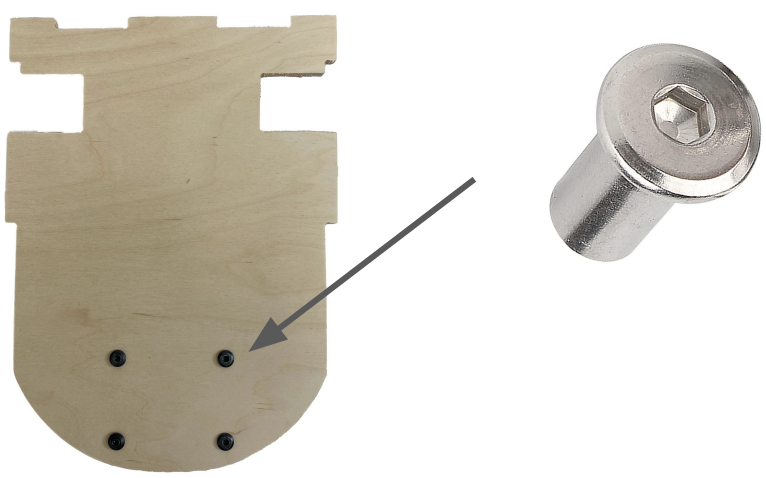
Flip the base (#1C) over so the engraved letter C is facing up. Place the Back Wheel atop the premade holes with the inserts now installed. Secure with 4 M6 screws (#7).
STEP #8 - Construct the Main Chair
IMPORTANT!
Make sure conic holes are on the outside of the chair (so screws securing the chair won’t stick out of the surfaces)! Relevant parts at this stage: back support (BOM #1A), footrest (#1E), and right/left side parts (#1F/#1G).
STEP #8.1
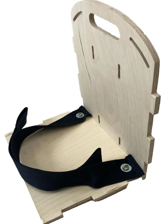
Connect the back support (#1A) and seat (#1B).
STEP #8.2
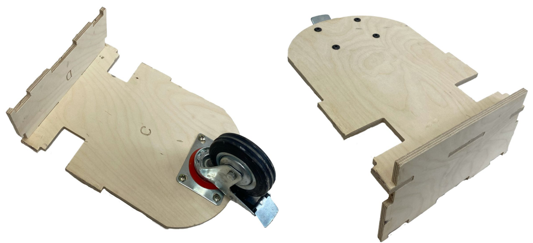
Connect base (#1C) and heel support (#1D).
STEP #8.3
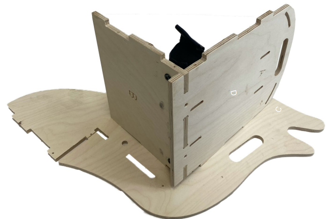
Connect the back support (#1A) and seat (#1B) to the right side (#1F).
STEP #8.4
Connect base (#1C) and heel support (#1D) to the right side (#1F).
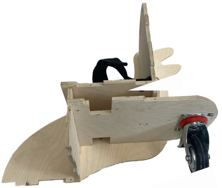
STEP #8.5
Connect the left side (#1G) parallel to right side onto the back support (#1A), seat (#1B), base (#1C), heel support (#1D), and footrest (#1E).
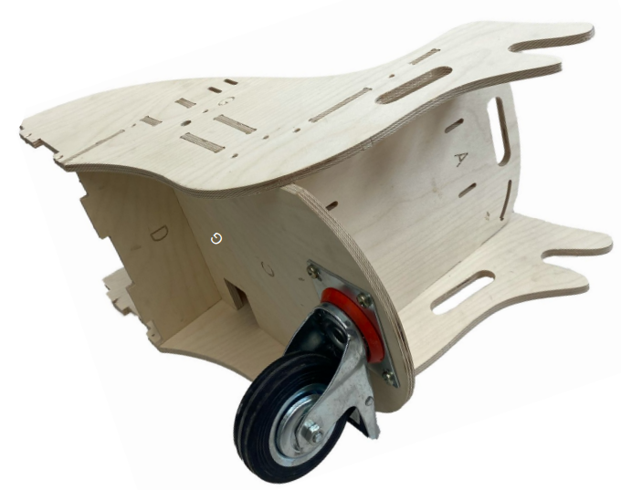
STEP #8.6
Connect the footrest (#1E) to the heel support (#1D) and right and left sides (#1F/#1G).
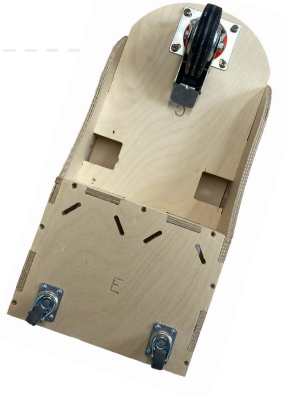
STEP #9
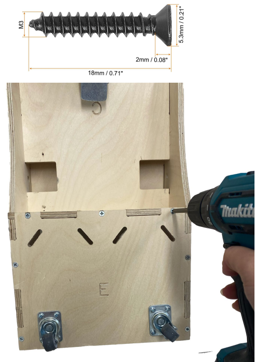
Use 2.5mm twist drill bit to drill pilot holes approximately 3mm deep through all conic holes [all parts with CNC-made holes aligning perpendicularly (90º) with other wood parts].
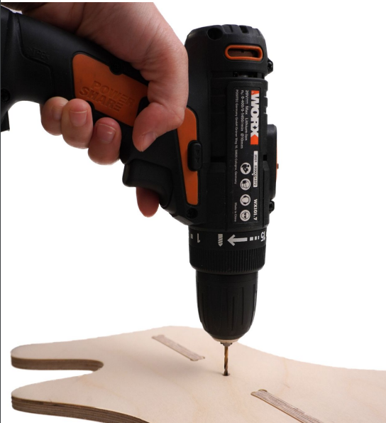
STEP #9.1
Screw 25 M4 20mm wood screws (BOM #2) into all pilot holes from the previous step.
1. Through the right/left sides (#1F/#1G) into the back support (#1A), seat (#1B), base (#1C), heel support (#1D), and footrest (#1E).
2. Through the back support (#1A) into the seat (#1B).
3. Through the footrest (#1E) into heel support (#1D) and right/left sides (#1F/#1G).
STEP #10 - Attach Foot Straps
Attach foot straps (#9) through the oval holes in the footrest (#1E).

STEP #11 - Place cushions on chair
Place seat padding and thread seat connection fabric into the lower slots of the back support.
Then place back padding and thread back connection fabric into the lower slots of the back support.
Tie bows to secure paddings in place.

STEP #11 - Place cushions on chair
Threat double sided hook and loop (#30) through side belt loops of back padding and slits on right and left wood sides. Close to secure in place.

STEP #12 - Attach Side Wheels To Chair
IMPORTANT! For safety!
Wheels need to be sufficient distance from wood so neither fingers nor forearms get caught between!
Connect both side wheels (BOM #16) to the right/ left sides (#1F/#1G) so the order of parts is as follows on the axle screw (#17) - from the outside of the chair to the inside:
1. Head of the axle screw (#17)
2. Side wheel (#16) - bearing indent
3. M12 nut (#19)
4. M12 washer (#18)
5. Wood - right/left sides (#1F/#1G)
6. M12 washer (#18)
7. M12 nyloc nut (#20)
Thats It!

We encourage you to share your makes and remixes of the Card Holder to inspire others, improve the design, and showcase customizations!
For further documentation and to explore other open source assistive tech solutions you can visit tomglobal.org
