
LDC - Locking Dovetail Connector for Festool MFT/3
Obliczymy ostateczną cenę na podstawie wybranego pliku. Sprawdzisz ją i zaakceptujesz przed płatnością.
Zapisane na tym urządzeniu.

A versatile locking dovetail interface, designed for strength, reliability, and easy printing.
- Ocena
- 0 / 5
- Polubienia
- 14
- Pobrania
- 37
- Wydruki
- 0
- Wyświetlenia
- 394
- Oceny
- 0
Aktualizacja u źródła:
Informacje o modelu
- Źródło
- Printables
- Kategoria
- Tools
- Licencja
- Creative Commons — Attribution
The Locking Dovetail Connector (LDC) is a versatile dovetail mounting solution designed specifically for the Festool MFT/3 aluminium rails. It is adaptable to a wide range of accessories and features a robust locking mechanism that prevents unintentional detachment.
Features
This model is thoughtfully designed to combine functionality, reliability, and user-friendliness. Each feature has been carefully engineered to meet the demands of real-world use while maintaining flexibility for customization and compatibility. From its robust locking mechanism to its optimized printability, the LDC is designed to deliver exceptional performance and ease of use.
Solid Grip
The LDC is engineered for stability. When mounted on the rail, it easily slides laterally while supporting substantial vertical loads. The design includes a retention nose on the upper angled surface, which counters upward motion and reduces bending forces on the hook-shaped sections. To ensure smooth locking and unlocking, the lower portion of the wedge interface incorporates a loose fit, adding flexibility during operation.

Locking Mechanism
The key focus of the LDC is its structurally reliable locking mechanism, designed to withstand typical operating forces without relying on friction-based methods. The geometry ensures that forces attempting to dislodge the accessory are channelled directly into the locking mechanism, to be neutralized within the lock itself, keeping it firmly in place during use.
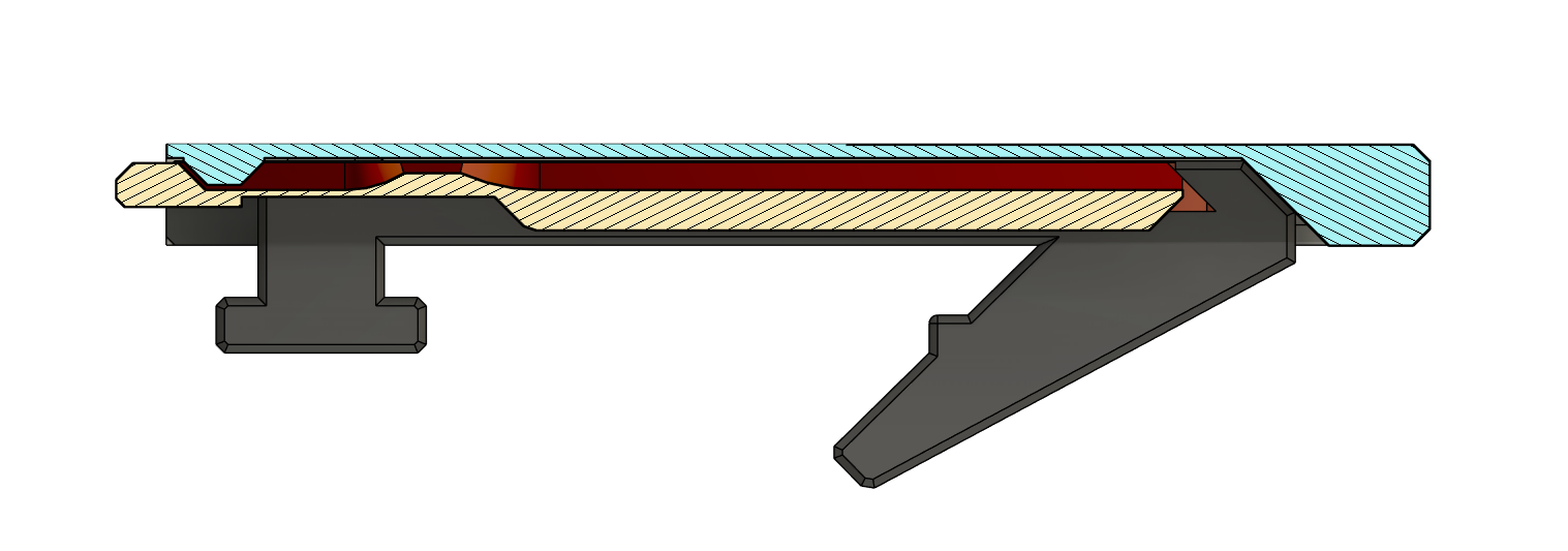
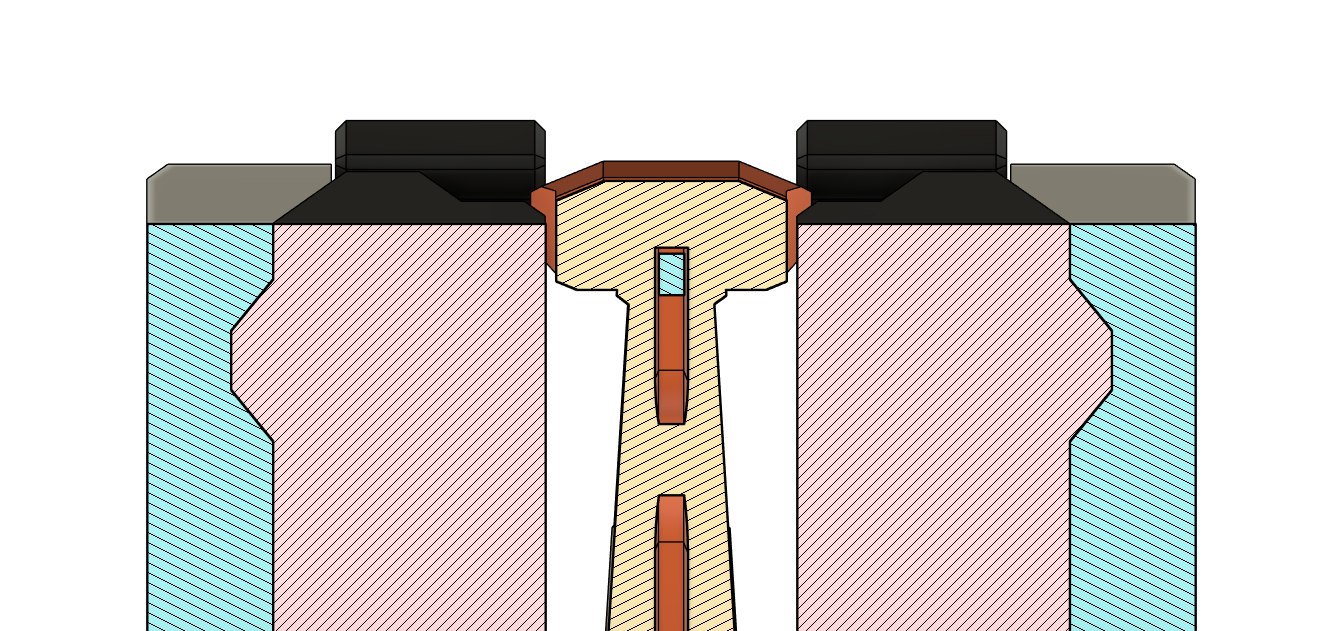
At the core of this design are two drafted tabs, positioned on either side of the connector. These tabs must move inward to disengage, but under load, their movement is entirely blocked by the central locking paddle. The paddle acts as a failsafe, preventing the tabs from yielding even under substantial force. This means the lock becomes stronger when the system is under load, as the design forces the applied stress into a locking configuration rather than allowing slippage.
To unlock, the paddle must be intentionally lifted, sliding into precisely designed recesses that create sufficient clearance for the tabs to move inward. This deliberate unlocking motion ensures that accidental disengagement is virtually impossible during regular operation.
Automatic Lift on Insert
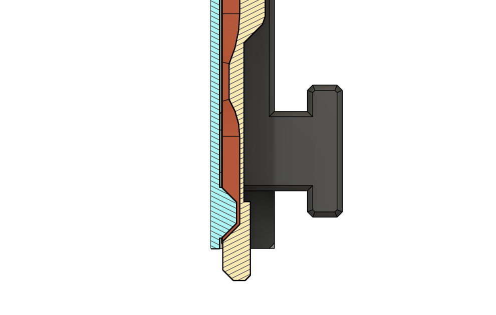
During testing, it became clear that a directional locking approach was required. Without directionality, the locking paddle could obstruct full seating of an accessory on the dovetail, potentially leaving it unlocked during operation. Also, this made the connector frustrating to use, especially during repeated insertions.
The implemented solution includes a small nib on the accessory side that interacts with the lever. As the accessory slides into place, the nib follows a guided slope, lifting the paddle just enough to allow the wedges to move inwards.
Optimal Layer Orientation
Layer orientation is critical for achieving maximum strength and durability in 3D-printed components. Every feature of the LDC is meticulously designed to align with this constraint, ensuring that applied forces act along the strongest axis (vertical) or are distributed across large surface areas.

The two wedge pieces are designed to be printed sideways, optimizing their load-bearing capacity. Details such as locking tabs, nibs, and wedge angles are tailored to allow for flexibility in printing orientation. All angles are set to 45 degrees, enabling accessories to be printed either upright (as with e.g. the Waste Bag Holder for Festool MFT/3) or flat (as demonstrated in the test piece shown in the photos). While the flat orientation may result in weaker components, it remains viable for many applications.
A Proposed Standard
This model is proposed as a standard for connecting accessories to the Festool MFT/3 and potentially other rail systems. While the current dimensions are suggested as a universal baseline, elements such as the width of the main body are open for further refinement and discussion within the community.
The locking tabs and nib are optional features that can be incorporated into accessories as needed. This flexibility ensures compatibility between one set of installed LDCs and a range of accessories. Thoughtful drafting of all surfaces enables us to adapt this system to diverse use cases.

The locking tabs are in line with the lower t-slot rail on the MFT/3 profile. All critical clearances are already included (0.2 mm)
Print Instructions
I suggest using PETG due to it's ductility, that I consider beneficial for an application like this. ASA/ABS will work fine as well, but are not as easy to print. Use your default 0.2 mm profile and increase the perimeter.
Customization
Find the Fusion 360 file in the download section. For designing custom accessories there are also step files for the necessary cutting tools (locking and non-locking).