
Functional Model of a European style railway screw coupler (UIC Schraubenkupplung)
Obliczymy ostateczną cenę na podstawie wybranego pliku. Sprawdzisz ją i zaakceptujesz przed płatnością.
Zapisane na tym urządzeniu.
Informacje o modelu
- Źródło
- Printables
- Kategoria
- Vehicles
- Licencja
- Creative Commons — Attribution — Share Alike
update: I just found an existing model in Scale I and II - obviously I previously did not find the proper search words. Still, that model is not functional (no threads) - see my "railway stuff" collection. I don't think a thread for this coupler is printable in your typical model scales.
----
update 2: added variations of round and square buffers that are spring-loaded using compression springs 35 x 7x 0.6mm (like this) - see picture
----
update 1: added a different (more square) buffer style - see picture
----
Browsing through Printables, I found very nice functional models of several automatic Railway couplers such as the Janney Coupler or the Scharfenberg Coupler.
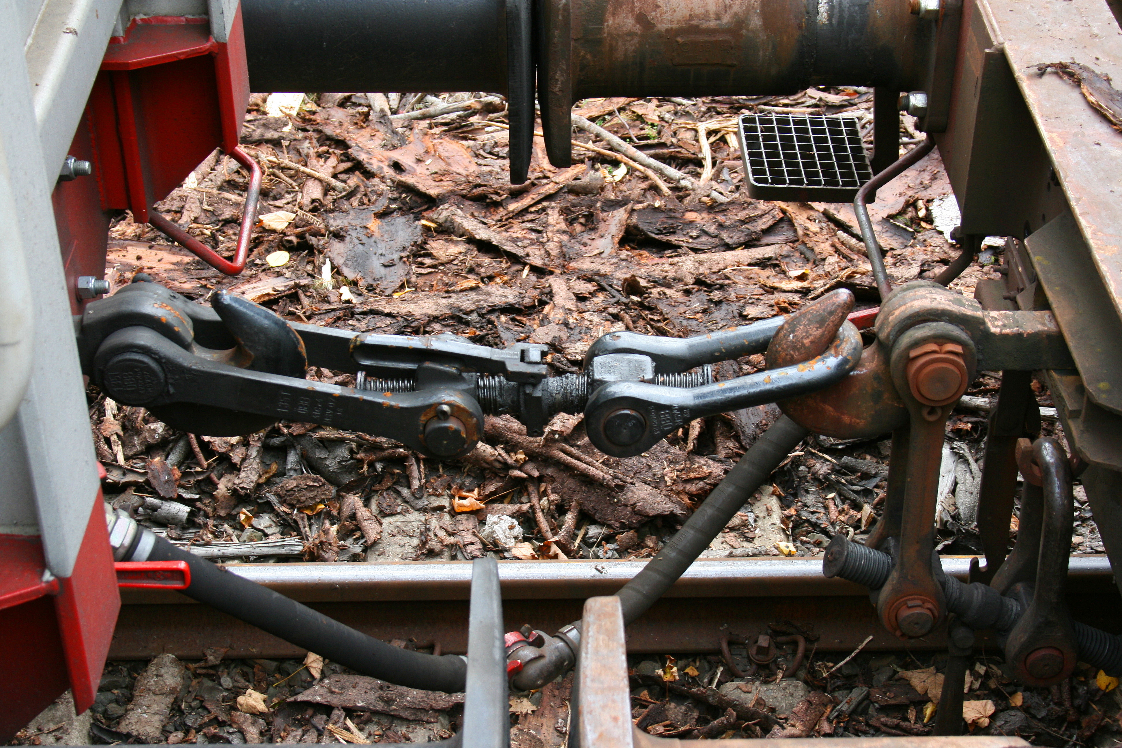
What I could not find, was a model of the ancient tech that is still widely used here in Europe by most standard gauge railways - the screw coupling (aka UIC Standard Coupling). So - I had to build one.
To get a functional model of a screw coupling you need more than just the coupler itself - buffers are essential to be able to push or break the train, the coupler itself only allows pulling action. So here is an entire coupling face of a railway car minus break lines or electrical connections. European railway cars have a coupling chain attached to either end of the car (only one of the chains per coupling is used at any point in time). I hope you like it.
BTW this is not a dimensional model, I just built this going by some pictures.
The spindle was made using the “Nut Job” scripts in OpenSCAD. It is a wunderful ressource!
Be careful when you assemble the spindle assembly - the two sides have different threads -one is “normal”, one has a ccw thread (and one of the nuts matches that). Try out which one is which carefully - PLA threads are easily ruined. You also need a dab of Superglue to attach the shakle at the fixed end of the coupling chain. Don't put any glue near the two nuts, these links need to rotate.
For reference - here is a pic of the real thing.:

---
update 2: optionale Versionen für gefederte Puffer ergänzt - Als Federn habe ich diese hier verwendet (35 x 7x 0.6mm).
----
update 1: variante mit modernen (eckigeren) Puffern ergänzt.
----
Hier auf Printables finden sich sehr schöne Funktionsmodelle verschiedener automatischer Kupplungen, z.B. die Janneykupplung und die Scharfenbergkupplung. Was ich nicht finden konnte war ein Modell der in Europa im Normalspurnetz weiterhin weit verbreiteten Schraubenkupplung (aka UIC Standardkupplung). So habe ich denn eines gebaut.
Natürlich braucht man für eine funktionierende Schraubenkupplung auch Puffer - die Kupplung selbst kann nur Zugkräfte übertragen, für Schubkräfte werden die Puffer benötigt. Und so habe ich hier eine Stirnseite eines Wagons angedeutet (ohne Bremsleitungen und Elektrik).
Dieses Modell ist nicht maßstabsgerecht und wurde auf Basis von Bildern erstellt.
Für die Spindel habe ich das “Nut Job” Script in OpenSCAD verwendet, eine wunderbare Ressource.
Vorsicht bei der Montage der Kupplungskette - die beiden Seiten der Spindel haben verschiedene Gewinde. Eine Seite ist “normal” (Rechtsgewinde), die andere hat ein Linksgewinde - ebenso wie eine der Muttern. Bitte vorsichtig ausprobieren, welche der Muttern auf welche Seite der Spindel passt. Ein Tropfen Kleber wird am festen Ende der Kupplungskette benötigt. Die Bolzen bei den beiden Muttern erhalten keinen Kleber - sie müssen drehbar bleiben.