
Klicky PCB probe for Creality K1
Obliczymy ostateczną cenę na podstawie wybranego pliku. Sprawdzisz ją i zaakceptujesz przed płatnością.
Zapisane na tym urządzeniu.

This modification allows to install the Klicky PCB probe onto Creality K1, improving bed mesh speed and precision.
- Ocena
- 5 / 5
- Polubienia
- 30
- Pobrania
- 146
- Wydruki
- 0
- Wyświetlenia
- 2021
- Oceny
- 1
Aktualizacja u źródła:
Informacje o modelu
- Źródło
- Printables
- Kategoria
- Creality Parts & Upgrades
- Licencja
- Creative Commons — Attribution — Noncommercial
This modification allows to install the Klicky PCB probe onto Creality K1, improving bed mesh speed and precision.
Video of the probe in operation:
Compared to the stock load cells, it has about 10-15x higher precision (standard deviation 0.002 mm, vs 0.02-0.03mm for stock K1 load cells).
Here's the output of the PROBE_ACCURACY macro:
probe accuracy results: maximum 4.001562, minimum 3.994141, range 0.007422, average 3.996133, median 3.995703, standard deviation 0.002063
Bed meshing speed is also significantly increased, since bed movement speed does not affect Klicky probe operation. A 6x6 point bed mesh is completed in 30 seconds.
WARNING: Without drag chain or lid modifications, rigid filaments may break in the PTFE tube while attaching/docking the probe with the lid closed. If you print carbon or glass fiber filled filaments, it is recommended to print a lid riser, or keep the lid off until the print starts.
BOM:
1x Klicky PCB probe kit
4x M3x12 SHCS
2x M3x20 SHCS
2x M3 heat inserts, 4-4.5mm long
2x M3 washers, 1mm thick
1x JST 1.25mm 3-5 pin connector
Probe wiring and configuration is described here: https://pellcorp.github.io/creality-wiki/klicky/
Assembly instructions:
- Print each of the 4 files attached here.
- Assemble the Klicky probe using hardware included in the kit, “Microswitch cover” and “Klicky mount” printed parts.
- Install the probe assembly on the toolhead, using two M3x12 screws, and two M3 washers between the probe and the toolhead.
- Take the “Dock mount” and melt the heat inserts into its holes.
- Insert one of the magnets from the Klicky kit into the "Probe dock".
- Attach the “Probe dock” to the “Dock mount” using two M3x20 screws.
- Remove the two front screws holding the left XY axis motor.
- Attach the dock to the left motor and its mount using two M3x12 screws, as shown on the picture below.
- Connect the Klicky probe to the toolhead board.
- Modify the printer configuration.
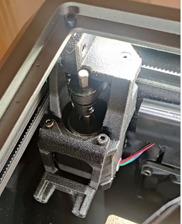
Assembled and installed dock