
CHAMELEON v2 - Modular Arcade Stick
Obliczymy ostateczną cenę na podstawie wybranego pliku. Sprawdzisz ją i zaakceptujesz przed płatnością.
Zapisane na tym urządzeniu.

A 40 x 20 x 5 cm fightstick with a perfectly rounded wrist rest and 24 possible permutations of joystick/button layouts.
- Ocena
- 5 / 5
- Polubienia
- 64
- Pobrania
- 382
- Wydruki
- 6
- Wyświetlenia
- 2518
- Oceny
- 3
Aktualizacja u źródła:
Informacje o modelu
- Źródło
- Printables
- Kategoria
- Video Games
- Licencja
- Creative Commons — Attribution
I am happy to announce that on 08.01.2025 I'll be launching CHAMELEON v3 and this version will be officially sunset! Huge thanks to everybody who reached out with requests and suggestions to help me improve CHAMv2 over the last 5 months!
RAF
UPDATE: CHAMv3 has launched! Click HERE for the new version!
Change Log
- JUL 2025
- End of development on CHAMELEON v2.
- JUN 2025
- Added plain versions of the Bottom Panels.
- MAY 2025
- Added a WASD Hitstick panel with no cutout.
- Added “Smash” panels. Full disclosure, I'm not a smash player, but I believe this should cover most bases. Recommend using my 24mm Plugs to fill the extra button holes (if they're extra… idk lol). I'm always open to suggestions!
- Fixed an unintended overhang in the PCB mount for the "Sega2P_R" panel.
- Minor updates to the assembly instructions for clarity.
- APR 2025
- Added 2 “HitStick” panels for the left hand. One has a WASD layout, and the other is the regular leverless layout. Note that these panels do not have PCB mounts as there isn't enough space for them.
- MAR 2025
- Added 2 more bottom panels with PCB mounts in the event you would prefer that configuration. As a side note, the sides are interchangeable so use whichever one fits your components better!
- FEB 2025
- Adjusted JLF mount height to bring base of balltop into the proper height from the top of the panel.
- Added a chamfer to the JLF mount for added strength.
- Added CrossCut layout - JLF panel on the left with tons of buttons on the right.
- Slight adjustments to locations of PCB mounts
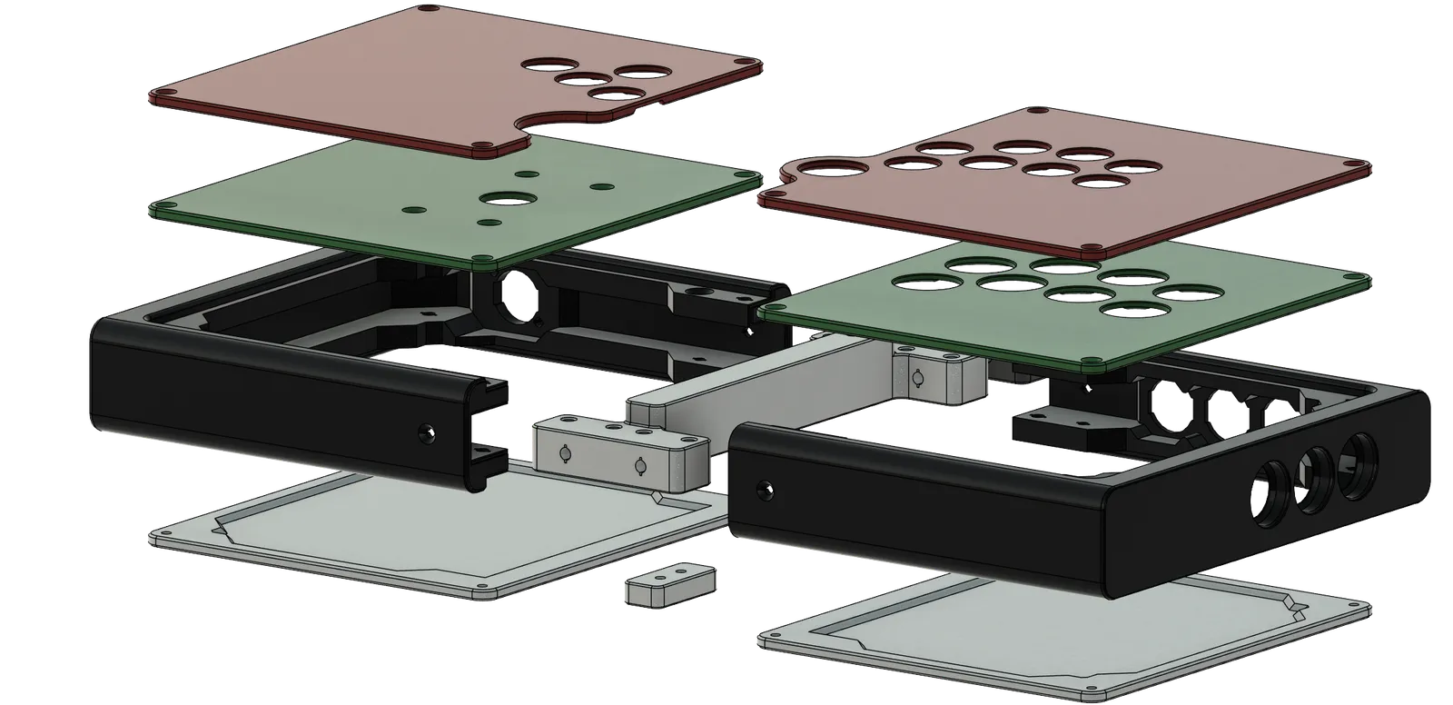 Introduction
UPDATE: CHAMv3 has launched! Click HERE for the new version!
This is version 2.0 of CHAMELEON, a modular fightstick. It has several changes from v1 that I believe make this a superior enclosure, but the old version will stay for historical purposes.
The new case utilizes the diagonal length of the build plate to allow for a larger enclosure. Those with a larger bed plate won't need to rotate it, though.
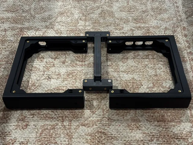
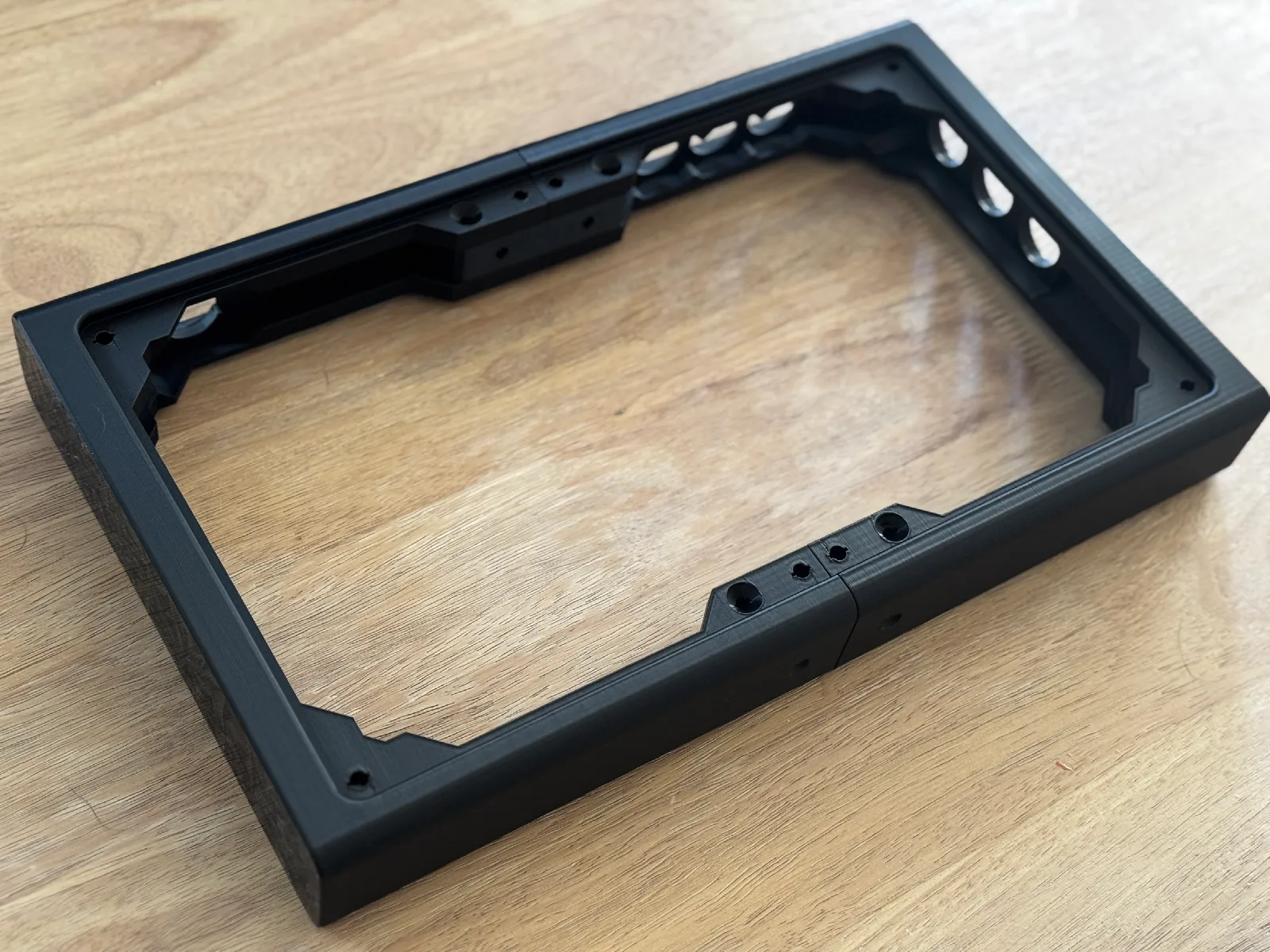
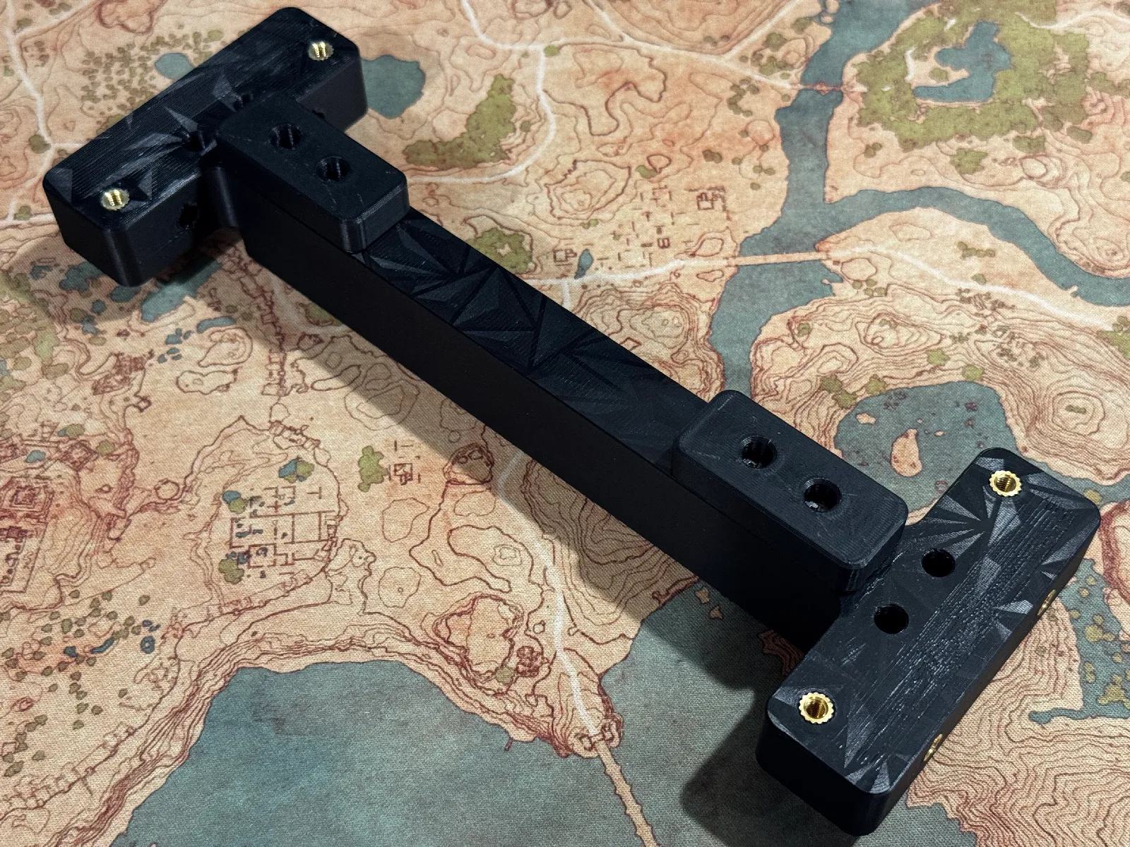
I changed the joining features of the two halves to be printed separately. And all M3 heat-serts have been replaced with M4 heat-serts (except those for the PCB and Neutrik). There is a non-connected joint for those using a non-split leverless layout, and an I-shaped joint for those who want maximum structural integrity and plan to use a joystick layout.
There are now panels on both sides of the case, which should help with lifting from the build plate, makes it easier to access the inside of the case, and provides another opportunity for customization.
The auxiliary buttons have been moved to the walls of the right half of the case, and are thoroughly recessed to prevent accidental button presses.
There are now several layouts, to include Sega 2P, VEWLIX, Leverless, WASD Leverless, and more to come. Also, I have designed them to be interchangeable for more options.
I designed the panels for Sanwa Snap-in Buttons and the Sanwa JLF joystick, but any low-profile button should work. The pins may need to be slightly bent on the buttons, but I was able to secure the panels without bending them.
Printing Suggestions
- Be warned, this enclosure will use close to an entire 1kg spool of filament!
- 4 Walls / 20% Cubic Infill / No Supports
- Only tested in PLA/PLA+, but other materials should work--provided they have minimal warping/shrinkage
- Designed for 220mm x 220mm x 250mm build volume
- Orient the 2 body pieces vertically in your slicer along the diagonal of the bed.
- Button panels should be oriented face down
- Recommend an enclosed 3d printer. The two halves of the body will likely lift from the build plate as the filament cools. Additionally ensure good adhesion to the build plate.
Materials Needed
- x28 M4 Heatset Inserts
- x16 M4x10mm Countersunk Screws (for panels)
- x12 M4x16mm Countersunk Screws (for joining features)
- x4 M3 Heatset Inserts (+2 if using for Neutrik)
- x4 M3x6mm Countersunk Screws (+2 if using for Neutrik)
- x4 Self-tapping #4 x 3/8" Screws (if using the I-Frame, but still optional)
- Arcade Stick PCB (GP2040-CE Advanced Breakout Board or Brook)
- Arcade Stick Buttons and/or Joystick
- Neutrik NAUSB
- Soldering Iron
Assembly
- PLAN & PRINT
- Decide what panel layouts you would like to use. This will determine which joint you can use.
- The I-Frame, while more stable, is not compatible with the leverless and hybrid layouts.
- If in doubt, print the “Open Joint”.
- After finalizing your decisions, print out all of the parts.

- INSTALL BODY HEAT SET INSERTS (HSIs)
- HSIs are installed via soldering iron – this will require a steady hand. Install HSIs as straight as possible into the hole.
- Recommend watching some YouTube videos on HSI installation if this is your first time. I like to insert until the final 1-2mm, then I use a flat metal object to push it flush with the hole and allow it to cool.
- As a general rule: none of the countersunk holes in this build are meant for HSIs.
- All countersunk holes are for screws, and will be referred to as “screw holes”.
- The body requires x16 M4 HSIs in total.
- Each half of the body requires x8 M4 HSIs that line up with the screw holes in the upper and lower panels.
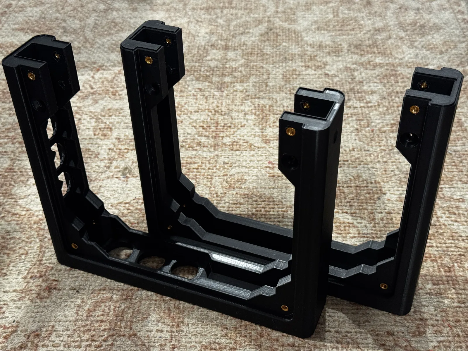
- INSTALL I-FRAME / OPEN JOINT HSIs
- The I-Frame and Open Joint require x12 M4 HSIs in total.
- x8 HSIs line up with the screw holes in the body (under the panels).
- x4 HSIs line up with the screw holes on the sides of the body.
- There are 4 extra holes to accommodate the use of a longer screw for the upper and lower panels – do not install HSIs into these!
- (For I-Frame) There are optionally some feet that connect to the I-Frame with x4 self-tapping #4 screws. This provides a bit more structure to the bottom of the case directly under the center of the bottom panels.

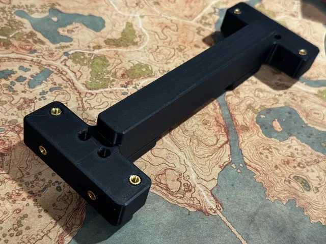
- (SEMI-OPTIONAL) INSTALL M3 HSIs
- x2 M3 HSIs install into the Neutrik holes on the left half of the body.
- Some folks will use a nut and bolt, but I like to use HSIs – whatever you prefer.
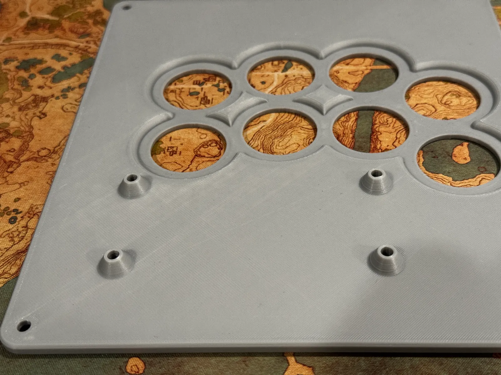
- x4 M3 HSIs install into your desired PCB mount on the upper or lower panels.
- Use whichever mount works best for your panel configuration.
- Honestly, I usually don't even install these. I snip a bit of toothpick flush to the top of the mount and use a self-tapping screw.

- ASSEMBLE FRAME
- Insert the joint into place and fasten x4 M4x16 screws through screw holes on the outside of the body into the joint.
- Fasten x8 M4x16 screws through the screw holes in the center of the body into the joint.
- For I-Frame, fasten x4 self-tapping #4 x 3/8" screws to join the feet to the I-Frame.

- INSTALL PANELS AND HARDWARE
- If you made it this far, then it's the home stretch!
- Install your controller hardware and the wire everything up. If it makes it easier, install the top panels first and then connect everything.
- Ensure all screws are fully tightened, and you're good to go!
Happy Printing!
RAF