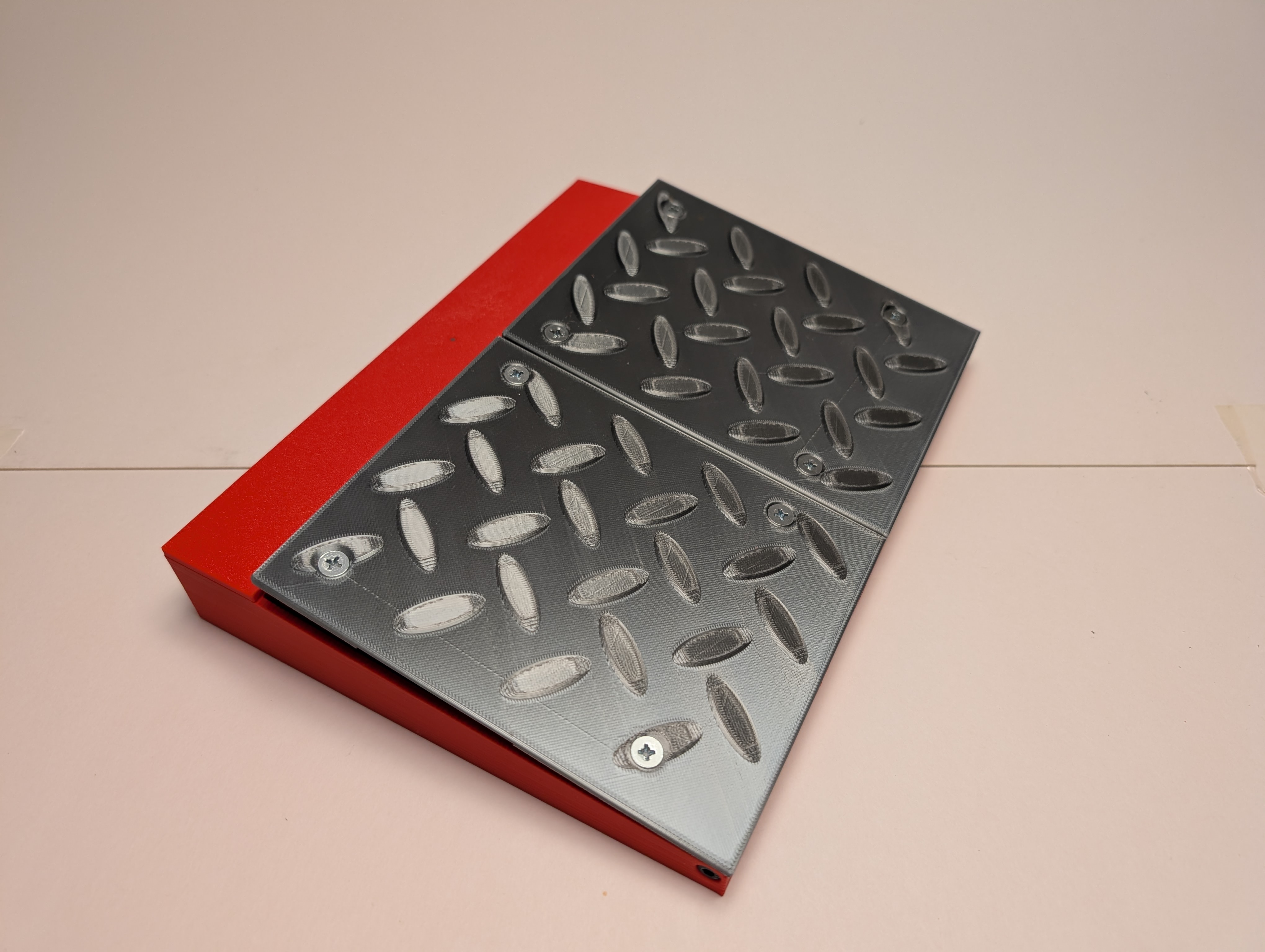
Perfectly Adequate Arcade Pedal (Wireless)
Obliczymy ostateczną cenę na podstawie wybranego pliku. Sprawdzisz ją i zaakceptujesz przed płatnością.
Zapisane na tym urządzeniu.

The is a completely redesigned Perfectly Adequate Arcade Pedal with wireless connectivity via Bluetooth or ESPNOW.
- Ocena
- 0 / 5
- Polubienia
- 22
- Pobrania
- 77
- Wydruki
- 2
- Wyświetlenia
- 846
- Oceny
- 0
Aktualizacja u źródła:
Informacje o modelu
- Źródło
- Printables
- Kategoria
- Video Games
- Licencja
- Creative Commons — Attribution — Noncommercial
"Perfection is the enemy of perfectly adequate."
- Saul Goodman
If you're like me and enjoy the occasional game of Time Crisis, but can't be compelled to spend $250 - $450 dollars for a refurbished original pedal or Sinden replica, and if you don't have the time, talent or sheer dedication to pull off a @Boojakascha approved ultimate pedal, then this might be for you.
***Introduction***
The new wireless Perfectly Adequate Arcade Pedal is designed to play games like Time Crisis and other lightgun games the way God intended–using a pedal to reload! That being said, it can also serve as a decent keystroke-sending-pedal for any foot based PC activity.
The P.A.A.P. works similarly to a wireless keyboard. The pedal connects to any PC via Bluetooth OR the ESPNOW protocol (not both at the same time) and will send a keystroke of the user’s choice when the pedal is pressed.
***Multiple Wireless Connection Strategies***
Again, the P.A.A.P. works by one of two wireless connection protocols: Bluetooth or ESPNOW. Bluetooth is ubiquitous, easy to set up and works great… usually. Bluetooth is also famous for being troublesome, inconsistent and laggy. Because of this, I highly recommend choosing ESPNOW as your wireless connection choice (shout out to @Nixx in the Sinden Lightgun Discord for raising my awareness). It is a bit more complicated to set up, requiring 2 ESP32s (transmitter and receiver) compared to Bluetooth’s single ESP32 requirement. However, once done, ESPNOW should offer a dedicated, solid and low latency interconnect to your PC or arcade.
***Two Pedal Configurations***
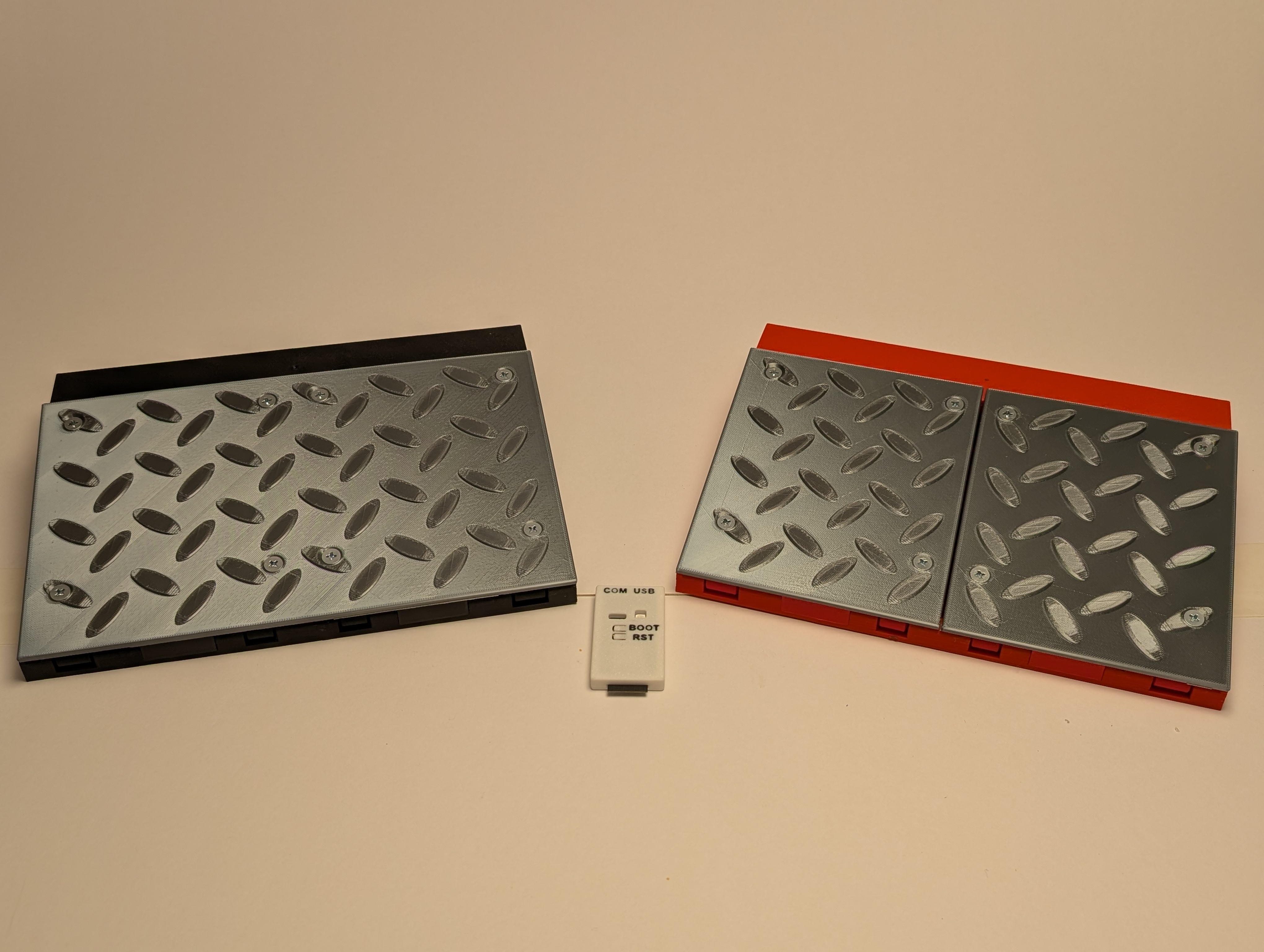
You have the choice of printing/building a dual or single pedal setup. A dual pedal setup is a serviceable choice for games like Time Crisis 5 and Too Spicy. It is also usable as a throttle and brake system for some older (and simpler) driving games. However, I recommend that you print the single pedal configuration. This is the right choice for the majority of pedal based shooters. Also, even if you are playing dual pedal shooters like Time Crisis 5, you will have a better experience IMO by simply printing two single pedal configurations (This configuration is only recommended with the ESPNOW protocol).
Recommended and Vetted Parts

Single Pedal Parts

Dual Pedal Parts
I have provided links to everything I used and tested in my build, but please be warned. The links to Amazon are large quantities and/or assortments. In other words, the links offer WAY more than you need for this project. I highly recommend that you check your local hardware store for the fasteners. America’s annoying allergy to the metric system can make finding some of the fasteners more difficult than necessary. Still, I have had great luck with Ace Hardware, Lowes and Home Depot. In that order.
***The BOM***
1 Firebeetle 2 ESP32-E board (Link)
1 ESP32-S3-DevKitC-1-N16R8 board (Link)
1 TP4056 USB-C Charging board (Link)
1 18650 Lithium battery (Link)
1 18650 lithium battery holder (Link)
4 springs (Link)
2 Micro switchs with roller arm (Link)
1 Rocker switch (Link)
1 Slider switch (Link)
8 M5x16mm Flat head screws with nuts (Link)
2 M4x30mm Hex head bolts with nuts (Link)
2 M4x45mm Hex head bolts with nuts (Link)
2 M3x12mm bolts with nuts (Link)
4 M3x8mm (#4x5/16) wood screws (Link)
4 M1.6x4mm screws (Link)
Soldering Iron, solder, flux, hot glue gun and AWG28 wire (Link or Link).
***Caveats***
I realize that there are many choices out there for switches, batteries, chargers, ESP32s, etc. Chances are, you already have a stash of these items and I encourage you to use whatever you're comfortable with. For those who wish to forge their own path, I have also provided a dual and single pedal configuration where the mounting holes and stand offs are removed. This will allow you to modify the pedal base in Freecad, Tinkercad, Fusion360, or whatever CAD program you prefer. If you’re not into CAD, drill holes the old fashioned way and glue the hell out of everything. Whatever you want. I'm sure it will work just fine.
For the transmitter board, I highly recommend the Firebeetle 2 ESP32-E. This board is excellent for battery powered applications because it is configurable to draw as little as 10uA of current while asleep. Other boards will draw 10x that, so choose wisely.
If I've convinced your to go with ESPNOW as your wireless connection strategy, for the receiver board, I recommend the ESP32-S3-DevKitC-1-N16R8. It has HID USB capability with the least amount of rigamarole. Most ESP32 boards do not have this capability without an additional daughter board. HID capability is a critical component of how the pedal works. As mentioned in the introduction, the wireless Perfectly Adequate Arcade Pedal essentially works like a wireless keyboard , just with the limitation of 1 or 2 keys.
***Printing Instructions***
First a note about printer dimensions (probably should have mentioned this sooner). The P.A.A.P. requires a minimum build plate of 250mm x 188mm.
1 - Print “1-Dual/Single Pedal Base.3mf”. I recommend the highest infill you're comfortable with. 100% if you can stomach it. Supports should not be required. (I've also provided a base without mounting holes or standoffs for those who wish to customize.)
2 - Print “2-Dual/Single Pedal Lever.3mf”. I recommend at least 50% infill to eliminate flex in the pedal. This will require minimal supports for the overhangs only.
3 - Print “3-Dual/Single Pedal Top.3mf”. I strongly recommend 100% infill. You will be stepping on this!
4 - Print “4-Dual/Single Pedal Lid.3mf”. I recommend at least 20% infill. (The default lid has a “light pipe” configuration. However, I've also provided an alternate file without one.)
5 - Print “5-Dual/Single Pedal Front Covers.3mf” and “5-Dual/Single Switch Retention.3mf”. I recommend at least 20% infill. Print these separately or together.
***Flash Code and Prepare the Electronics***
Instructions for how to flash the provided ESP32 code are beyond the scope of these instructions. With that said, I recommend installing the Arduino IDE and watching any number of YouTube videos to learn how to use it. Specifically, acquaint yourself with flashing code to an ESP32 and how to install libraries. The following libraries will be needed for this project:
BleKeyboard.h
esp_now.h
WiFi.h
USB.h
USBHIDKeyboard.h
Without these libraries, you will certainly encounter errors with the provided code.
One more tip that might save you some grief. Enable the “Huge App” partition scheme in the Arduino IDE tools menu if you encounter errors about there not being enough space on your board.
1 - Flash the RECEIVER ESP32 board with he instructions detailed here: https://randomnerdtutorials.com/get-change-esp32-esp8266-mac-address-arduino/
The only purpose of this step is to acquire the RECEIVER board’s unique MAC address. This is absolutely critical for ESPNOW. (If you’re not using ESPNOW, you can skip this step I suppose). Once you’ve acquired the RECEIVER MAC address, store it somewhere safe. You will need it for the next step.
2 - Flash ESP32 transmitter code to your chosen transmitter board.
Be sure to include the MAC address of the receiver that you just extracted. Locate the section of the transmitter code that states “// ESPNOW peer address” and replace the ## characters with your receiver's MAC address values.

While the code is open, you may wish to customize the micro-controller pins, default keys, and/or the inactivity timer.

3 - Flash the receiver ESP32 board code. (Yes, you will be overwriting the MAC address extraction code.)
4 - Solder/connect the electronics outside of the pedal base as much as possible. Leave only the power switch unattached (save for last). Believe me when I tell you that trying to solder with the components installed in the base will be a bad time. A hot iron and melty plastic do not mix well, so I strongly suggest you keep a healthy distance between them.
Follow the wiring diagram below. The pedal transmitter code assumes the I/O configuration as shown, but if you know what you’re doing, this can easily be changed to your preferences.
***IMPORTANT NOTE (1-1-2026)***
After feedback, I've altered the schematic to route power from the 3V3 pin to VCC. Also, it has come to my attention that the latest documentation for the Firebeetle 2 ESP32 board (illustrated below), recommends the use of the PH2.0 connector for power. However, I've had multiple reports of it working using the VCC pin.


I recommend that you learn from my mistake here and do NOT install the headers on the ESP32. Just solder the wires directly to the board.

The hot glue is not necessary, but 24 gauge wire can be a bit fragile. Your call.
5 - Carefully slot the TP4056 charging board into position on the pedal base. Once fully flush to the outer wall, firmly press down and you should feel a noticeable click into place.

6 - Attach the 18650 battery holder using 2 M3x8mm (#4x5/16) wood screws (Link). Hot glue would also work just fine, especially if you have a slightly different holder.

7 - Attach the ESP32 transmitter board using 4 M1.6x4mm screws (Link) OR hot glue. The mode selection slider switch is hopefully already attached to the micro-controller as shown below. (Note: The hole pattern is made for the Firebeetle 2. Alternate boards may not align.)
Now is also the time to install the rocker switch and finalize the wire connections per the wiring diagram above.


8 - Mount the slider switch using 2 M3x8mm (#4x5/16) wood screws (Link) and the switch retention piece from your last 3d print. Be sure to get the polarity correct.

9 - Route the wires for the micro switches as shown below. Don’t forget the common wire!

10 - Install the micro-switch(s) with roller hinge. You do NOT require the roller on your switch, but at minimum I would recommend a hinge arm. Install using 2 M3x12mm bolts with nuts (Link).


***Assemble the Pedal***
1 - Insert 4 M4 nuts into the pedal base hinge. They should slot into place without too much effort.


2 - Place 2 springs into the lever and insert 8 M5 nuts. The lever is designed for the nuts to be a tight fit. If you have trouble squeezing them in, use a longer M5 screw and draw them into place with a screwdriver. (An electric screwdriver or drill will make your life much easier here.)
Quick tip: If you want a little bit more resistance when pressing the pedal, try doubling up the springs.
If you’re building the dual pedal, there will be two smaller levers and a 4 spring requirement.

3 - While holding springs in place with your fingers, carefully install the lever and guide the springs into receptacles on the base. Additionally, be sure the overhangs on the lever go under the pedal base cut outs. (Sorry, I didn’t get a photo of this step, but I think it will be fairly obvious how to proceed. I trust you can figure it out!)
4 - Fasten the lever to base. Ensure that all wires are free from being pinched by the lever (especially on the dual pedal). Start by installing 2 M4x30mm Hex head bolts (Link) into the center locations using an Allen key. Do not over tighten! Snug and flush is the goal.


5 - Finish the lever installation with 2 M4x45mm Hex head bolts (Link) into each end. Again, snug and flush. No need to over tighten.


6 - Install the front hole covers. They just snap into place. These are optional finishing pieces.

7 - Attach the faux-diamond top plate using 8 M5x16mm flat head screws (Link).


8 - Install 18650 lithium ion battery and prepare the electronics compartment cover. There are two cover files provided--with and without “light pipe”. The light pipe will direct the charging indicators of the TP4056 to be visible to the user. Red for charging, and blue for fully charged. This is not a “power indicator”. It is a charging indicator. If you go with a a light pipe, you will need a tiny amount of clear PETG filament.


9 - Attach the electronics compartment cover. Start with the outer ends and firmly snap it into place.

10 - If using ESPNOW, I suggest installing the ESP32-S3-DevKitC receiver board into a case. I recommend this one: https://makerworld.com/en/models/159341-esp32-s3-devkitc-basic-case?from=search#profileId-765978
The COM port is for flashing code. The USB port is for connecting to the PC/Arcade.


***Operation***
As mentioned, the P.A.A.P works in 1 of 2 modes--Bluetooth or ESPNOW. Simply select the mode with the slider switch as shown below. Changing the mode will not take effect until the power is cycled (turned off and then back on).
The pedal will automatically go to sleep after 10 minutes of inactivity. It will “wake up” when the pedal is depressed. (If using a dual pedal configuration, the left pedal will wake the system. )
By default, the single/left pedal will transmit the letter “l” (small “L”) and the right pedal will send the letter “r”. This can easily be customized within the transmitter code.

The USB-C port is only for charging. Plugging it into your computer will charge the battery, but it will not be recognized as a USB keyboard. If you want a pedal with a wired connection, check out the original P.A.A.P.
Speaking of charging, if using the Firebeetle 2 ESP32 board, I expect you to have months of battery life. Probably even longer. As for other boards, your mileage will vary, especially if it implements a non-configurable power LED.

Tread Lightly
I do not know what the load limitation of this pedal is. It will depend on the infill settings that you use and the quality of your layer adhesion. I recommend that you tread lightly. Literally.

Enjoy
If you have trouble, I am happy to give a reasonable amount of support in the Sinden Lightgun pedal Discord channel. (Shout out to everyone there with a special thanks to Hexxed and Nixx for the support and inspiration.)