
Raspberry Pi Expansion Board for Ender-3 V3 SE
Obliczymy ostateczną cenę na podstawie wybranego pliku. Sprawdzisz ją i zaakceptujesz przed płatnością.
Zapisane na tym urządzeniu.

This expansion board for Raspberry Pi enables remote control of a printer with the OctoPrint and the Enclosure plugin.
- Ocena
- 0 / 5
- Polubienia
- 33
- Pobrania
- 34
- Wydruki
- 0
- Wyświetlenia
- 1486
- Oceny
- 0
Aktualizacja u źródła:
Informacje o modelu
- Źródło
- Printables
- Kategoria
- Creality Parts & Upgrades
- Licencja
- GNU General Public License v2.0
After completing this upgrade, I have 4 more assembled boards available. If you're interested in this upgrade but don't feel confident in soldering the board and wires, feel free to message me. I can sell the ready-to-use kits for 30 Euros without the power supply, or 40 Euros with it. I can ship across Europe.
My other Ender-3 V3 KE/SE parts & upgrades:
- LED Light Bar
- LED Light Bar combined with Anti Shake Construction
- Raspberry Pi Case combined with Display Mount
About:
This expansion board for Raspberry Pi enables remote control of a printer with the OctoPrint and the Enclosure plugin.
It provides the following functionality:
- Turning the printer on and off remotely.
- Turning the LED light bar on and off, as well as adjusting its brightness remotely.
- Connecting up to 5 buttons for controlling printer functions.
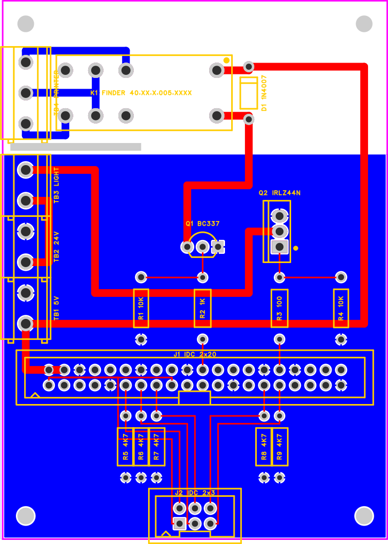
All components are through-hole for easy soldering, requiring no special equipment or advanced skills. The board connects to a Raspberry Pi with a single 40-pin ribbon cable for a simple setup.
Gerber files for ordering the PCB (I ordered mine from JLCPCB, and it cost me 4.53 EUR, including shipping and taxes), as well as the 3D model for printing the board case, are included.
Before you begin:
To assemble this upgrade for your printer, a basic understanding of electricity is required. Without this knowledge, you risk damaging your printer, Raspberry Pi, or worse — electrical hazards. Please proceed with caution.
Schematic:

PCB:
BOM:
I've added links to all of the components I used. I purchased them from Lemona Electronics (not an AD), and they offer delivery across Europe.
| Component | Specification | Quantity | Total, EUR |
|---|---|---|---|
| R1, R4 | 10 kΩ 0.25W | 2 pcs. | 0.40 |
| R2 | 1 kΩ 0.25W | 1 pc. | 0.40 |
| R3 | 100 Ω 0.25W | 1 pc. | 0.40 |
| R5, R6, R7, R8, R9 | 4.7 kΩ 0.25W | 5 pcs. | 0.40 |
| Q1 | Any NPN BJT transistor in TO-92 package e.g. BC337, etc. | 1 pc. | 0.09 |
| Q2 | Any logic-level N-channel MOSFET transistor in TO-220 package e.g. IRL3705N | 1 pc. | 2.99 |
| J1 | IDC 2x20 male connector or 2x20 pin header with 2.54 mm pitch | 1 pc. | 0.89 |
| J2 | IDC 2x3 male connector or 2x3 pin header with 2.54 mm pitch | ||
| TB1, TB2, TB3 | Any screw terminal block with 5.08 mm pitch and 2 pins e.g. AKZ120/2-5.08 | 3 pcs. | 1.80 |
| TB4 | Any screw terminal block with 5.08 mm pitch and 3 pins e.g. AKZ120/3-5.08 | 1 pc. | 0.79 |
| D1 | Any 1N400x series diode e.g. 1N4004, 1N4005, 1N4007, etc. | 1 pc. | 0.12 |
| K1 | Any Finder 40 series 5V relay e.g. Finder 40.61.9.005.0000 | 1 pc. | 3.99 |
| IDC 2x20 female connector | 2 pcs. | 1.58 | |
| 40x0.089 mm² ribbon cable | 1 m. | 3.89 | |
| Any 5V 3A power supply e.g. Mean Well RS-15-5 | 1 pc. | 9.80 | |
| Spade terminal 4.3 mm red for 0.5-1.5 mm² wire | 10 pcs. | 0.90 | |
| Pin terminal 1.9 mm red for 0.5-1.5 mm² wire | 10 pcs. | 0.90 | |
| Spade terminal 4.3 mm blue for 1.5-2.5 mm² wire | 10 pcs. | 0.90 | |
| Female blade terminal 4.8 mm for 0.5-1.5 mm² wire | 10 pcs. | 0.90 | |
| Female blade terminal 4.8 mm for 1.5-2.5 mm² wire | 10 pcs. | 0.90 | |
| Ring terminal 4.3 mm for 0.5-1.5 mm² wire | 10 pcs. | 0.90 | |
| Wire 1x0.75 mm² brown | 1 m. | 0.30 | |
| Wire 1x0.75 mm² blue | 1 m. | 0.30 | |
| Wire 1x0.75 mm² yellow-green | 1 m. | 0.30 | |
| Wire 1x0.5 mm² black | 2 m. | 0.50 | |
| Wire 1x0.5 mm² red | 2 m. | 0.50 | |
| Braided sleeving 4 mm | 2 m. | 1.18 | |
| Total, EUR: | 36.02 | ||
Build instruction:
- Solder all components according to the PCB silkscreen. Don’t forget to clean the board from flux using isopropyl alcohol.


- If, like me, you decided to power the Raspberry Pi from the power supply specified in the BOM, solder or crimp the wires as shown in the pictures:


- Choose the appropriate case and print it. Two versions of the case are provided with the model. If you decided to use the power supply specified in the BOM, select the file for the power supply and board. If you plan to power the Raspberry Pi via a USB power supply, choose the case designed only for the board. Secure the board and the power supply to the case and connect the wires from the previous step as shown in the images.


- Disconnect the wires connecting the socket on the printer's chassis to the power supply and grounding.


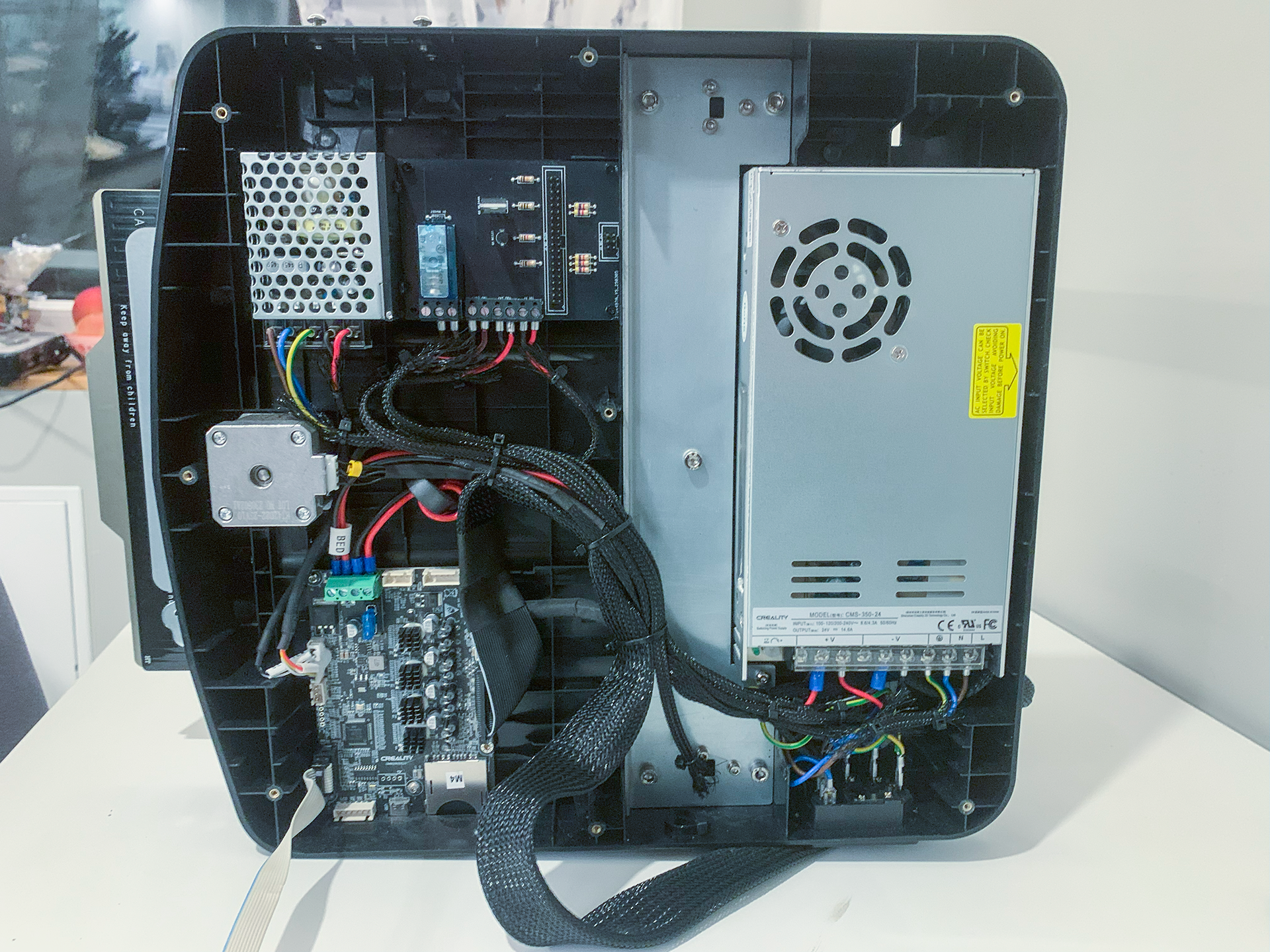
- Take the wires connected to the board and connect their fork-terminals to the socket on the printer’s chassis. Then, attach the ring-terminal to the grounding.

- Place the case with the board and the power supply as shown in the image, then secure the wires with zip-ties.

- Connect the Raspberry Pi using a 40-pin cable with IDC-connectors, like the one used for IDE hard drives.
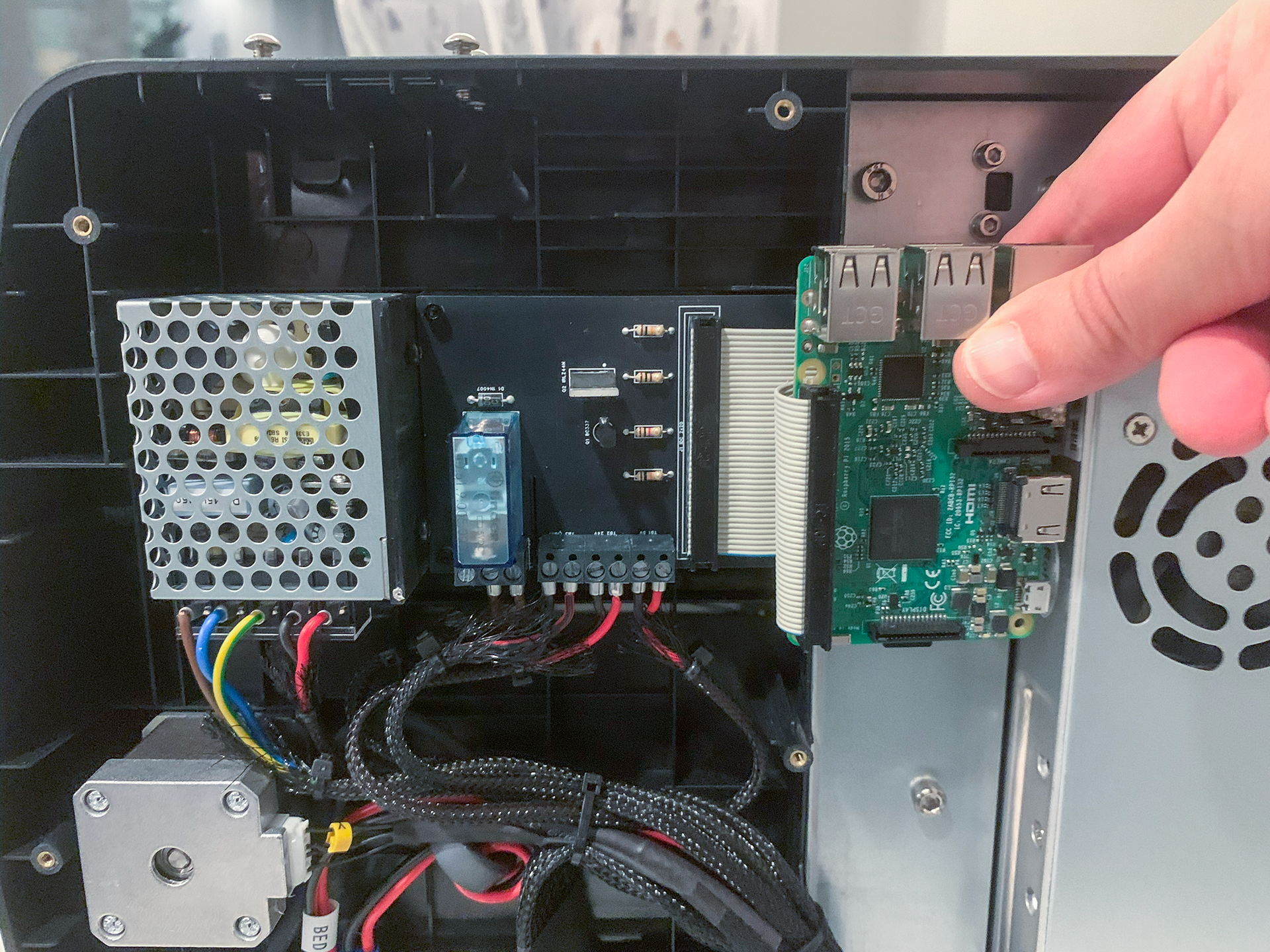
- To neatly position the Raspberry Pi, you can use my Raspberry Pi Case combined with the Display Mount.
- To set up the Enclosure plugin for OctoPrint, specify the following GPIO numbers for outputs:
| Output Type | Label | IO Number |
|---|---|---|
| Regular IO | Printer | 25 |
| Regular IO/PWM | Light | 12 |
- And the following - for inputs: 17, 27, 22, 5, 6. Use Input Pull Resistor: Input Pulldown.
If you've made it this far, you’ve probably made a make of my model. Feel free to share it with me and leave a comment!