
Zenity : a 2.5m glider
Obliczymy ostateczną cenę na podstawie wybranego pliku. Sprawdzisz ją i zaakceptujesz przed płatnością.
Zapisane na tym urządzeniu.

Zenity is a 2.5m RC glider fully built from scratch. Wing span : 2.5m weight : 1.2kg
- Ocena
- 0 / 5
- Polubienia
- 41
- Pobrania
- 278
- Wydruki
- 0
- Wyświetlenia
- 2401
- Oceny
- 0
Aktualizacja u źródła:
Informacje o modelu
- Źródło
- Printables
- Kategoria
- RC & Robotics
- Licencja
- Creative Commons — Attribution — Share Alike
I designed the Zenity to start building a RC glider using fiberglassed foam wings.
Following this guide you can build your own !

In flight (la dune du Pilat, France)

She flies also in the mountains !
Plan
Everything was designed using CAD model

This helped me to position Center of Gravity according to modelization made with “PredimRC”.
PredimRC is a fantastic Excel spreadsheet helping you to fully modelize your RC plane. It is a quite complex program but it simply worths spending a few hours to study it and understand its features !
Basically with PredimRC you can input your plane geometry and wings profiles. All the needed computations will be done for you including “Xfoil” virtual wind tunnel and position of Center of Gravity of your plane and a lot more!
Here is the result for the Zenity: (excel file available into the “files” section).

On the top left corner I have entered the wing geometry. The wings profiles have been designed by Mark Drela their names are “AG25/AG26:AG27 bubble dancer”. They were specifically designed for thermal gliders.
Mark Drela is a famous MIT ingeneer more than deeply involved into airfoil design and now Director of Wright Brothers Wind Tunnel.
Top view of my Zenity was cloned from the Arthobby Serenity plane.

I have only reused the wings spans and fuselage length.
And these lengths have been entered into PredimRC with the AG 25/26/27 profiles. Then result of predimRC were put into my CAD model and a fuselage was put under the wings coupled with the relevant V tail / wing incidence angle.
I wanted the wings cut from a foam block using the “hot wire” technics, then fiberglassed into a vacuumbag.
For the fuselage I wanted to use 3 carbon arrows glued together to form a strong tail boom. Vtail itself would be also cut into foam and fiberglassed.

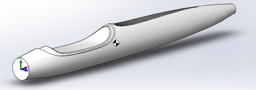
The fuselage would be 3D printed and then fiberglassed:
Hot wire cutting the wings from foam
Wing is cut into 2 parts :

· First center panel 650 mm long uses AG25 and AG26 profiles
· Wing tip panel 600 mm long uses AG26 and AG27 profiles
· Total half wing is 1250 mm so a wing span of 2.5m
Profiles are reversed to be cut trailing edge first as they are aligned

We will use Jedicut free software to produce the Gcode for the foam cutter.
Here are the settings to enter into jedicut for each panel (2 center ones + 2 wingtips)
Center panel
create a new wing and enter the profiles. Enter the chords lengths (the spar will be added later)
Start by creating a new "wingCut"
Then you will have to fill this screen:
- import dxf files one for the root the other for wing tip
- adjust the chord lengths
- don't forget to leave the "Cut Wizard" box ticked. It's mandatory to have jedicut running well
- adjust the kerf values (named thickness) for root and wing tip.
- and if you want to insert a carbon rod as on the wing drawing follow next paragraph...

As you can see on this screen, you can import "flipped" profiles (that is with trailing edge on the left instead of leading edge). I did it because
- cut will start by the trailing edge and won't stop at the leading edge
- hotwire will "pull" foam when finishing the cut at the trailing edge/bottom skin. This will insure a very clean and thin trailing edge
- my wings are aligned at le trailing edge. It's thus easier to align the hotwire on the foam block
Of course jedicut doesn't know that I have flipped the profiles and will call "leading edge" what is for me "trailing edge"...
Now position wing into your foam block (I have a 83cm hotwire)

Finally add the carbon spar as a “cut out”
Cut outs
open the "Ribs Manager" menu
And don't be impressed by this screen. Let's take an example of a carbon rod with a 7.5mm diameter that you want to insert on the bottom skin of the wing (exactly as displayed above)
- select the round cutout
- place it "below"
- enter the "depth" (half the diameter + margin), enter the diameter, and position the cut out on the X axis (origin at the left of the profile, usually at the leading edge)

you can select different positions and diameters for root and wing tip (upper right tick boxes -note that "parallel to leading edge" means for my flipped profile "// to trailing edge"-)
Configure the foam block and wing length
Open the "Cutting Wizard" menu
and enter mainly
- your wing length
- position of your foam block in your bed
- enter sweep back value (here 0 as I am aligned on the trailing edge)

cutting path
You are almost ok for cutting your wing, but you must first tell jedicut how you want to do it
Open the "Cycle of cut Manager" menu
And you will get this default screen
Cut will start by a vertical blue line then enter the foam horizontally, then cut the upper skin from 1 to 2, then go vertically, then go back to origin and cut the bottom skin with the same path
It can be useful for wing laminating but it's long...
So I prefer to cut my wing in a single path starting from the trailng edge, cutting the top skin then going back to the trailing edge.
Hopefully you can delete most of the path (delete button at the bottom right corner) and reverse cutting direction for horizontal or vertical lines (change the sign), and even reverse the path for upper or lower skin
- 10 mm entry horizontal line
- upper skin from 1 to 2
- lower skin from 2 to 1
- 10mm exit horizontal line
check that this path is also properly applied (it should) to the wing tip profile (tick box "wing tip").

You may notice that the "cut out" of the carbon rod is not displayed... But, trust me, it will be present into the Gcode file !
If you have more complex dxf files where synchronization points must be added between the two profiles, it's totally feasible under this menu via "key points". explore these possibilites by yourself !
You are now ready to export the Gcode
exporting the Gcode
This is done via the "Cut" menu

Don't forget to tick the "Manual heating control" box and to enter the correct percentage of heat you want to apply to your hotwire (0 to 100%). More complex and advanced options exist into Jedicut to keep track of temperature for each material or speed... explore these options by yourself!
Before cutting this panel we will do the same for the other panels
Wing tip panel


No spar into this panel (simpler !)

Right wings
We could do the same process for the right wing center and tip panels. But another much simpler solutionwill be toreuse strictly the Left files abov and swap the connections of the stepper motor to symetrize the profiles (right will be left !)
But if you don't dare to do this here are the settings for the right wings!
Center panel

Wing tip panel

The jedicut files are attached into the files section of this project
Cutting the wings
Still into Jedicut software you will configure your foam cutter machine to output Gcode
Go to the option tab and check that you have these axis names

Go to the option menu
then in the communication tab select Gcode and leave all the other values unchanged.
(Jedicut was working with old PC and sending motion to the parallel port of the PC... We will not use Jedicut to control our machne as it will be done by FluidNC.)
Now check in the "GCode" tab that it looks like this screen
You will find the location where the Gcode files will be saved and the conventions for axis naming (do not change these namings they work fine)
The two planes for the profiles will be
- X1Y1 = XY
- X2Y2= AZ
Now click on the "CNC Controller" tab and enter the length of your hotwire
don't change other values, they were used by the parallel port controller. If you want to be clean you can however enter the Length of the X axis!
That's it you machine is now fully configured.
Now launch the cut for each panel

The gcode file will be output in the selected directory. I rename them with .nc extension.

Using the foam cutter
We have gcode files ready to be used by our foam cutter.
I have designed a foam cutter electronics board, and you can build your own easily following this guide : https://hackaday.io/project/199287-fluidnc-4-axis-foam-cutter-controller
Here is a picture of my foam cutter: “2 X/Y planes moving the cutter in a synchronized manner” !

Using GRBLhotwire as a Gcode sender
RCKeith is maintaining a Gcode sender totally specialized for foam cutters.
Everything is more or less on a single screen:
- you can connect after selecting the com port
- you can load and run the Gcode file
- you can jog the two axis independently or simultaneously
- the two profiles are displayed (still a little deformed but looking like originals)
- the hotwire can be controlled and the temperature can be tuned
Drawbacks are minimal:
- the profiles are not perfectly scaled and look still a little weird (but cutting is perfect !)

Ok we have now foam wings cleanly cut
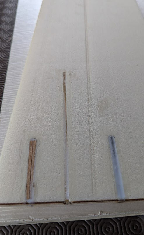
Here is a close up of this wing section with carbon rod inserted and "plywood reinforcement profile" glued on the edge. These profiles have been laser cut. Dxf files are available into the “files” tab. Gluing these profiles to the wings will help a lot to precisely aign the wing sections and to cut the slots to insert the joiners (aluminium pipes)

Next important step will be to laminate the wings
Laminating the wings
Follow these steps
filling the grooves with micro balloon and epoxy

vacuum bagging the wings
(see this project: https://hackaday.io/project/196665-a-vacuum-pump-with-an-old-fridge-motor
keep the wing flat while vacuum bagging...


Prepare wing joiners and trim the edge

cut the PeelPly hinge for ailerons and flaps : https://www.thingiverse.com/thing:6898947

cut the servo bays


and install the servos, glue the laser cut “wingServoHolder” to attach the servo into the tray.
3D print the fuselage and fiberglass it
Fuselage is cut into 4 parts, printed vertically in "spiral vase" mode, then glued and fiberglassed.


This the help of the template file, trace the cockpit on the fuselage and cut it carefully with a diamond disk. Install servo tray for elevator and rudder. Add also the “lip” into the fuselage to keep the cockpit in place

cut the V tail, fiberglass it

Glue it in place on the 3d printed part, Add reinforcement with fiber glass around the bottom of the tail.

fix the V tail on the tail boom (3 arrows carbon spars). You can rotate “freely” the tail, when alignement with the wings is perect fix this rotation with cyano glue drops between the 3 arrows.
motor and propeller
integrate all the electronics and check Center of Gravity
- Propeller : 10x6 folding propeller
- battery : 3s lipo 220mAh
- motor : AOKFLY AM2312-X 2312 980KV
- ESC : Hobbywing Skywalker 30A
now paint the fuselage, add decals and trim all this: Ready To Fly!
