
Portable High-Power LED Spotlight
Obliczymy ostateczną cenę na podstawie wybranego pliku. Sprawdzisz ją i zaakceptujesz przed płatnością.
Zapisane na tym urządzeniu.

A portable and modular LED spotlight consuming in excess of 100 Watts, powered by a LiPo, and featuring a Fresnel lens
- Ocena
- 0 / 5
- Polubienia
- 11
- Pobrania
- 33
- Wydruki
- 0
- Wyświetlenia
- 632
- Oceny
- 0
Aktualizacja u źródła:
Informacje o modelu
- Źródło
- Printables
- Kategoria
- Electronics
- Licencja
- Creative Commons — Attribution — Noncommercial
Introduction & Overview
This project is based around the 100 Watt LED modules that can be purchased online. I've played around with these over the years, and I finally decided to make a proper project based on this part. This was inspired by the desire to have a high powered spotlight for Airsoft (MILSIM) events and for general fun.
This is my first time combining one of these LED modules with a Fresnel lens. The intention of the lens is to collimate the light to increase the ‘throw’ of the beam, thus resulting in a spotlight effect. In practice, the beam diverges more than I like, but it's still a decent result. Maybe a more expensive lens would perform better. Initial testing has shown I can (reasonably) light up trees at the other end of a 100 metre field.
The LED must be actively cooled, and in this design this is done via an AMD Wraith CPU cooler. I chose this cooler as I had one lying around, and they can be bought for cheap. You could use something else, but you will have to rework at least one of my parts.
The Spotlight is powered via a large(ish) 6S LiPo battery, with various electronic protection components being deployed, including a Battery Management System (BMS) board. I estimate that the chosen LiPo can power the Spotlight for approx. 1 hour at full power. But In reality, this is probably more like 45 minutes. This also depends on the set maximum output voltage of the boost converter, if you set this higher, the LED will draw more power, and the battery will run out of charge faster.
>>> Lithium batteries are dangerous, re-create this project at your own risk! <<<
The whole device is controlled by a main case mounted potentiometer with built in switch. Turn the knob to turn on the Spotlight, and then turn further to increase the power output (brightness). Simple.
The LiPo is held in an internal cage with a clip, and the back cover is held in place with magnets, for easy access to the LiPo.
There is a handle too, with some adjustment (as it has to span across some parts). I designed the handle to support one of these Picatinny rails, so something like an optic can be attached.
There is also a ¼"-20 UNC threaded insert found on the bottom side of the Spotlight, so that it can be attached to a tripod or similar.
The whole Spotlight is fastened together with M4 and M3 cap head bolts and nuts (I've used washers in some places). I've used slot in nuts where possible, rather than using heat set threaded inserts. If I provide assembly instructions, then I will specify exactly which fasteners need to be used and where. But if you have a similar kit of fasteners that I used (see the attached Bill of Materials (BoM)), then you'll be fine.
The inside of the Spotlight has dovetails on each side, running down the entire length of the interior. The internal printed parts slot into these dovetails. This is so that the front lens can have some focal adjustment. But this also makes assembly fairly straightforward and the design somewhat modular. For example, if a different lens is used, then it might just be the case that only one minor sub assembly needs to be replaced.
Project Breakdown
This project has two main elements, the 3D Printed Components (case, holders, etc.), and the purchased components (electronics, lens, etc.).
Purchased Components
As with any project like this, you'll want to make sure that the electronic guts work first before getting the big parts printed. See the attached BoM for what you will need for this project, how much they cost me to buy, where I got them from, and why they are needed, if at all.
Below is the circuit diagram. I made two circuit boards using strip board (Veroboard) to make assembly easier. The dimensions of these boards can be found in the diagram. Some of the printed parts are designed around these dimensions, so if you chose a different size, or go down a different route altogether, you may have to rework some of my parts.
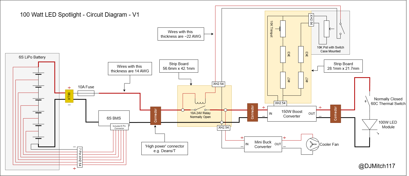
Potentiometer Board
The boost converter has a small 10k Ohm trim pot soldered onto the boost convert PCB. This is what is normally used to control the output voltage of this converter. I removed this and soldered this onto a piece of strip board with some additional resistors, as shown in the circuit diagram. The main 10k Ohm pot connects to this board via a connector.
This board then allows the maximum voltage being applied to the LED to be set at a fixed value via the trim pot, and then the main pot can be used to vary the voltage to the LED from low, to this maximum (low to high brightness).
The procedure to set the maximum voltage applied to the LED is:
- Have nothing but a DC voltmeter connected to the output of the boost converter
- Connect the main pot to the pot board, and connect the pot board to the boost converter
- Apply the same nominal voltage of the battery you will be using to the input of the boost converter, keeping in mind that the converter will only boost voltages, and has a limited input range
- Turn the main pot all the way clockwise (maximum resistance)
- Now turn the trim pot until the voltmeter reads your desired output voltage
- Done. Now when you turn the main pot in the other direction, the voltage decreases.
You may wish to under voltage your LED (~28 Volts) to lower it's heat output and increase battery run time, or you may wish to over voltage (~32 Volts) your LED to push it to it's limit and get the most brightness out of it. Over volting, especially with inadequate cooling, may damage your LED module.
3D Printed Components
There are two .3mf files. These are Orca Slicer project files.
- LED Spotlight V1.3mf
- LED Spotlight TPU V1.3mf
Both .3mf files contain all the parts you need, the print orientations, and the settings I used. I used a 0.4 mm nozzle, on my Bambu Labs X1C, for the entire project.
The first .3mf contains all of the main parts. Parts on plates “Lens Holder” and “LED & Board Holder” should be printed using a temperature resistant material. For this application PETG will suffice. Don't use something like PLA for these parts. The rest can be printed using whatever material you like, but I went with ASA for the whole of this project, so the entire Spotlight was temperature resistant and tough.
The second .3mf contains the optional parts that should be printed in a flexible filament (e.g. TPU 95A). These parts will make the spotlight more water resistant for use outdoors.
I used ERYONE High Speed Filament ASA for the first .3mf, and SUNLU 95A TPU for the second .3mf.
Assembly Instructions
Heat Sink Prep
Holes
I drilled and tapped four M3 holes into the Wraith heat sink, each 34mm apart, as per the LED hole dimensions/locations. This is so I could mount the LED directly to this part. Thermal paste was applied in-between the two parts before they were fastened together. I found it difficult to drill and tap these holes in the exact correct locations, even with a drill press. In the end, three out of four holes lined up, so I only used three M3 bolts.
Thermal Switch
If you are including a thermal switch with your Spotlight, then before you apply thermal paste and mount the LED to the heat sink, you will need to decide how you will mount the thermal switch. Ideally, this is embedded into the heat sink very close to the centre of the LED. If I had a milling machine, or more skill with a Dremel, I would have milled a slot on the top surface of the heat sink for the switch to slot in and be flush with the top surface of the heat sink whilst the large flat side of the switch is in contact with the centre rear of the LED.
Instead, what I did was drill a hole through the centre of heat sink where the diameter of the hole was slightly greater than the diameter of the thermal switch. I then mounted the LED with thermal paste. After this, I inserted thermal paste into the centre hole, put thermal paste onto the switch, and then inserted the switch into the hole, so that the top of the switch was in contact with the rear centre of the LED. The switch is held in place by the thick paste and screw heads trapping the wires. This is not the best way to do this, it's just what I did for my prototype!
Assembly Continued…
If I get some interest with this project I will provide full assembly instructions at a later date.