
Baseball_Pitcher_Project.V01
Obliczymy ostateczną cenę na podstawie wybranego pliku. Sprawdzisz ją i zaakceptujesz przed płatnością.
Zapisane na tym urządzeniu.
Informacje o modelu
- Źródło
- Printables
- Kategoria
- Mechanical Parts
- Licencja
- Creative Commons — Attribution — Noncommercial — Share Alike
Project did with Onshape.
Edit: the contest for the arduino pet accessory ended 20 min after this post… so yeah… one month of work, destroyed… because I live in Canada and I thought that it finished at 00:00 in my country and not in Europe…
Please…3D prints the parts in PET-G CF for better solidity, the black belt should be in TPU (70A-90A)
This project uses .5in Hex bearing and 8mm bearing (the hole in the center)
French:
Afin de finaliser ce projet à temps, je n'ai pas pu tester mon projet à 100%, j'ai seulement pu tester la gearbox, donc si vous finalisez le projet avant moi ou bien qu'il y a des problèmes, veuillez me le souligner, je ferai de mon mieux pour améliorer ce projet, aussi, à chaque amélioration que j'y apporterai, j'actualiserai la version de ce projet.
Vue d'ensemble :
Ce projet est un lanceur de balles de baseball motorisé utilisant trois roues pour projeter des balles à grande vitesse avec différents effets. Il a été spécialement conçu pour combiner performance, fiabilité et sécurité d'utilisation.
Pourquoi j'ai créé ce projet :
J'ai conçu ce lanceur pour mon frère, qui est actuellement dans un programme collégial de baseball. Le but était de l'aider à s'entraîner efficacement, tout en évitant que mon père ne se blesse au bras en lançant manuellement des centaines de balles. Grâce à ce système, mon frère peut recevoir des balles à haute vitesse de manière répétitive et sécuritaire, sans dépendre d'une personne pour lui faire des lancers.
Ce que ce projet accomplit :
Vitesse de tir : Le lanceur est capable d'envoyer des balles jusqu'à 85–90 mph, une vitesse idéale pour simuler de vrais lancers en match.
Effets variés : Grâce aux trois roues indépendantes, il est possible d'ajuster la rotation des balles pour créer différents effets (balle rapide, curveball, slider, etc.).
Polyvalence : Le système est également compatible avec toute balle de 75 mm de diamètre, ce qui ouvre la porte à d'autres utilisations, comme lancer des balles pour des chiens à l'extérieur pour les faire jouer.
Particularités spéciales du projet :
Système de propulsion à trois roues motorisées pour un meilleur contrôle de la vitesse et des effets. (possibilité à deux roues (- d'effets possibles))
Utilisation d'engrenages personnalisés pour augmenter le couple et maintenir une vitesse stable au moment du tir.
Possibilité d'ajuster facilement la vitesse et le type d'effet pour s'adapter à différents types d'entraînement ou de jeu.
Conception robuste et impression 3D optimisée pour la durabilité et la performance.
Utilise des moteurs CIM (un par roue) ainsi qu'une batterie 12V comme dans les compétitions de FRC
POUR FAIRE CE PROJET, S'IL VOUS PLAÎT LE FAIRE EN ÉTANT SÉCURITAIRE !!! (je n'ai aucun responsabilité si vous vous blessez lorsque vous utilisez les mécanismes, ce sont des roues tournants très rapidement avec des moteurs qui peuvent atteindre jusqu'à 5500 RPM)
Donc utilisez des câbles de 14 AWG ou 16 AWG lorsque directement connecter entre la batterie et les moteurs ainsi qu'un fusible de 20–30A entre la batterie et votre montage pour sécuriser. Des…
| MOSFETs |
| Pouvant gérer votre courant moteur (par ex. >20A si besoin, style IRLZ44N ou IRF540N) |
UTILISER UN ARDUINO N'EST PAS NÉCESSAIRE !!!
Vous pouvez utiliser des Digital PWM DC Motor Speed Controller w/ 0-100% Adjustable Display, 6V/12V/24V DC (un par moteur) au lieu d'un Arduino avec des Mosfets ou autre controlleur
MAIS ATTENTION, DANS TOUS LES CAS VOUS AUREZ BESOIN DE BATTERIES 12V (normal quoi…)
Avec Arduino:
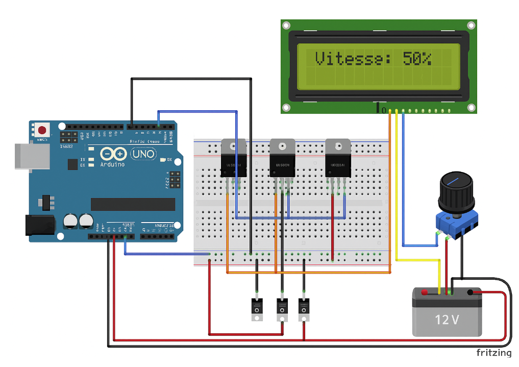
Vous aurez besoin de 3 MOSFETs, un potentiomètre-poussoir, un écran LCD (type 16x2), trois résistances de 220–330Ω (pour le Gate du MOSFET) ainsi qu'un Arduino ayant une compatibilité 12C.
Pour alimenter l'Arduino, vous pouvez utiliser un Buck Converter 12V-5V ou bien utiliser directement son alimentation Jack avec un Step-down (5V)
Code Arduino:#include <Wire.h>#include <LiquidCrystal_I2C.h>
// Configuration de l'écran LCD (adresse I2C 0x27, peut varier)LiquidCrystal_I2C lcd(0x27, 16, 2);
// Pinsconst int potPin = A0; // Potentiomètre analogiqueconst int buttonPin = 2; // Poussoir du potentiomètre (digital)const int motor1Pin = 3; // PWM Motor 1const int motor2Pin = 5; // PWM Motor 2const int motor3Pin = 6; // PWM Motor 3
// Variablesint potValue = 0;int motorSpeed = 0;bool motorsOn = false;bool lastButtonState = HIGH; // Pull-up style boutonunsigned long lastDebounceTime = 0;unsigned long debounceDelay = 50; // Anti-rebond bouton
void setup() { // Initialisation des pins pinMode(buttonPin, INPUT_PULLUP); // Bouton en mode pullup interne pinMode(motor1Pin, OUTPUT); pinMode(motor2Pin, OUTPUT); pinMode(motor3Pin, OUTPUT);
// Initialisation de l'écran lcd.init(); lcd.backlight(); lcd.setCursor(0, 0); lcd.print("Lanceur Pret!");}
void loop() { // Lecture du potentiomètre potValue = analogRead(potPin); motorSpeed = map(potValue, 0, 1023, 0, 255); // Adapter à PWM
// Lecture du bouton poussoir (avec debounce) int reading = digitalRead(buttonPin); if (reading != lastButtonState) { lastDebounceTime = millis(); } if ((millis() - lastDebounceTime) > debounceDelay) { if (reading == LOW) { // Bouton pressé motorsOn = !motorsOn; // Toggle moteur ON/OFF } } lastButtonState = reading;
// Contrôle des moteurs if (motorsOn) { analogWrite(motor1Pin, motorSpeed); analogWrite(motor2Pin, motorSpeed); analogWrite(motor3Pin, motorSpeed); } else { analogWrite(motor1Pin, 0); analogWrite(motor2Pin, 0); analogWrite(motor3Pin, 0); }
// Affichage sur l'écran LCD lcd.setCursor(0, 1); lcd.print("Vitesse: "); lcd.print(map(motorSpeed, 0, 255, 0, 100)); // Pourcentage pour affichage lcd.print("% "); delay(100); // Petite pause pour la stabilité}
🛠 À vérifier avant de téléverser :
Matériel Détail
LCD I2C Adresse I2C souvent 0x27 ou 0x3F (tu peux la scanner si besoin)
Potentiomètre Utilise A0 pour le signal analogique + un digital pin (2) pour le bouton
MOSFET Assure-toi qu'ils sont logiques "level" (ex: IRLZ44N) pour bien commuter avec l'Arduino 5V
Alimentation Utilise une source externe pour les moteurs, pas l'Arduino directement
🧩 Schéma rapide :
Potentiomètre : milieu vers A0, extrémités 5V et GND. Bouton vers D2 (avec pull-up interne).
MOSFETs :
Drain → moteur
Source → GND
Gate → Arduino PWM pin via une résistance de 220–330Ω
LCD branché sur SDA/SCL (pins A4-A5 sur Uno R4 ou broches dédiées sur ton modèle)

Déclaration d’utilisation d’un MML : (ChatGPT)
Afin de générer mon code à temps ainsi que pour m'aider dans la rédaction de ce que vous aurez besoin, j'ai utilisé ChatGPT pour rédiger plusieurs parties de la description, si le code ne marche pas (ce qui peut arriver), je m'en excuse.
English:
In order to complete this project on time, I wasn't able to fully test my project; I was only able to test the gearbox. So, if you complete the project before me or if there are any issues, please let me know. I'll do my best to improve this project. I'll also update this project with each improvement I make.
Overview:
This project is a motorized baseball pitching machine that uses three wheels to launch high-speed baseballs with varying spin. It was specifically designed to combine performance, reliability, and safety.
Why I Created This Project:
I designed this pitching machine for my brother, who is currently in a college baseball program. The goal was to help him practice effectively while also preventing my father from injuring his arm by manually throwing hundreds of baseballs. With this system, my brother can safely and repeatedly receive high-speed balls without relying on someone to throw them to him.
What this project achieves:
Firing Speed: The launcher is capable of launching balls up to 85–90 mph, an ideal speed for simulating real game throws.
Varied Spin: Thanks to the three independent wheels, the rotation of the balls can be adjusted to create different spins (fastball, curveball, slider, etc.).
Versatility: The system is also compatible with any 75 mm diameter ball, which opens the door to other uses, such as throwing balls for dogs outdoors for play.
Special Project Features:
Three-wheel motorized propulsion system for better speed and spin control. (two-wheel option (fewer spins possible))
Uses custom gears to increase torque and maintain a stable speed when firing.
Speed and spin types can be easily adjusted to suit different training or game styles.
Robust design and 3D printing optimized for durability and performance.
Uses CIM motors (one per wheel) and a 12V battery, just like in FRC competitions.
TO MAKE THIS PROJECT, PLEASE DO IT SAFELY!!! (I am not responsible if you injure yourself while using the mechanisms; these are very fast-spinning wheels with motors that can reach up to 5500 RPM.)
So, use 14 AWG or 16 AWG wire when connecting directly between the battery and the motors, and a 20–30A fuse between the battery and your setup for safety. MOSFETs
Can handle your motor current (e.g., >20A if needed, like the IRLZ44N or IRF540N)
NO ARDUINO REQUIRED!!!
You can use a Digital PWM DC Motor Speed Controller with 0-100% Adjustable Display, 6V/12V/24V DC (one per motor) instead of an Arduino with MOSFETs or other controllers.
BUT BE CAREFUL, IN ANY CASE YOU WILL NEED 12V BATTERIES (normal, that is...).
With Arduino:
You will need 3 MOSFETs, a push-pull potentiometer, an LCD display (16x2 type), three 220–330Ω resistors (for the MOSFET gate), and an Arduino with 12C compatibility.
To power the Arduino, you can use a 12V-5V buck converter or directly use its power jack with a step-down (5V).
Arduino Code:#include <Wire.h>#include <LiquidCrystal_I2C.h>
// Configuration de l'écran LCD (adresse I2C 0x27, peut varier)LiquidCrystal_I2C lcd(0x27, 16, 2);
// Pinsconst int potPin = A0; // Potentiomètre analogiqueconst int buttonPin = 2; // Poussoir du potentiomètre (digital)const int motor1Pin = 3; // PWM Motor 1const int motor2Pin = 5; // PWM Motor 2const int motor3Pin = 6; // PWM Motor 3
// Variablesint potValue = 0;int motorSpeed = 0;bool motorsOn = false;bool lastButtonState = HIGH; // Pull-up style boutonunsigned long lastDebounceTime = 0;unsigned long debounceDelay = 50; // Anti-rebond bouton
void setup() { // Initialisation des pins pinMode(buttonPin, INPUT_PULLUP); // Bouton en mode pullup interne pinMode(motor1Pin, OUTPUT); pinMode(motor2Pin, OUTPUT); pinMode(motor3Pin, OUTPUT);
// Initialisation de l'écran lcd.init(); lcd.backlight(); lcd.setCursor(0, 0); lcd.print("Lanceur Pret!");}
void loop() { // Lecture du potentiomètre potValue = analogRead(potPin); motorSpeed = map(potValue, 0, 1023, 0, 255); // Adapter à PWM
// Lecture du bouton poussoir (avec debounce) int reading = digitalRead(buttonPin); if (reading != lastButtonState) { lastDebounceTime = millis(); } if ((millis() - lastDebounceTime) > debounceDelay) { if (reading == LOW) { // Bouton pressé motorsOn = !motorsOn; // Toggle moteur ON/OFF } } lastButtonState = reading;
// Contrôle des moteurs if (motorsOn) { analogWrite(motor1Pin, motorSpeed); analogWrite(motor2Pin, motorSpeed); analogWrite(motor3Pin, motorSpeed); } else { analogWrite(motor1Pin, 0); analogWrite(motor2Pin, 0); analogWrite(motor3Pin, 0); }
// Affichage sur l'écran LCD lcd.setCursor(0, 1); lcd.print("Vitesse: "); lcd.print(map(motorSpeed, 0, 255, 0, 100)); // Pourcentage pour affichage lcd.print("% "); delay(100); // Petite pause pour la stabilité}
🛠 Check before uploading:
Hardware Details
LCD I2C I2C address often 0x27 or 0x3F (you can scan it if needed)
Potentiometer Use A0 for the analog signal + a digital pin (2) for the button
MOSFET Make sure they are logic level (e.g., IRLZ44N) to properly switch with the 5V Arduino
Power Supply Use an external power source for the motors, not the Arduino directly
🧩 Quick schematic:
Potentiometer: middle to A0, ends 5V and GND. Button to D2 (with internal pull-up).
MOSFETs:
Drain → Motor
Source → GND
Gate → Arduino PWM pin via a 220–330Ω resistor
LCD connected to SDA/SCL (pins A4-A5 on Uno R4 or dedicated pins on your model)
MML Usage Declaration: (ChatGPT)
In order to generate my code on time and to help me write what you'll need, I used ChatGPT to write several parts of the description. If the code doesn't work (which can happen), I apologize.