
Soldering Fume Extractor
Obliczymy ostateczną cenę na podstawie wybranego pliku. Sprawdzisz ją i zaakceptujesz przed płatnością.
Zapisane na tym urządzeniu.
Soldering fume extractor with 127mm^2 carbon activated filter
- Ocena
- 0 / 5
- Polubienia
- 9
- Pobrania
- 34
- Wydruki
- 0
- Wyświetlenia
- 268
- Oceny
- 0
Aktualizacja u źródła:
Informacje o modelu
- Źródło
- Printables
- Kategoria
- Electronics
- Licencja
- Creative Commons — Attribution — Share Alike
An easy to assemble and service soldering fume extractor with a carbon activated filter. I had some leftover pc fans from my build that wanted to repurpose. This design uses no additional hardware apart from some magnets and should be quite easy to print on most printers. No supports or such are required.
My Print Settings
- material: PLA matte
- layer height: 0.2mm
- infill: 15% 3d honeycomb
- walls: 3
- supports: none
Bill of Materials
These are the materials I used for the build
- 24x magnets 6mm x 3mm (alternatively some 6mm x 6mm dowels could probably be printed using cylinderes directly in the slicer)
- some cables to connect the components
- 1x 127mm x 127mm x 8mm carbon activated filter
- 1x usb-c decoy
- 1x step down buck converter
- 1x pwm pc fan controller
- 1x 120mm 12v fan
Assembly Instruction
For the electronics, I followed this excellent model's guidance https://makerworld.com/en/models/1019135-soldering-fume-extractor-usb-c-open-source. This setup works quite nicely, though some chargers/cables don't seem to like outputting anything more than the default 5v. I'm not sure if it's due to the usb-c decoys I got or something else, and I'm way too ignorant on the matter to have any informed guess as to why it happens. Anyhow be sure to try different cables/chargers if there are any troubles making the fan spin.
- press fit magnets in all insets

- solder the usb c decoy to the buck converter input. Also set the buck converter to output 12v if it is adjustable

- solder the buck converter output to the pwm controller input

- insert the pwm controller in the hole of the electronics box and secure with the provided nut
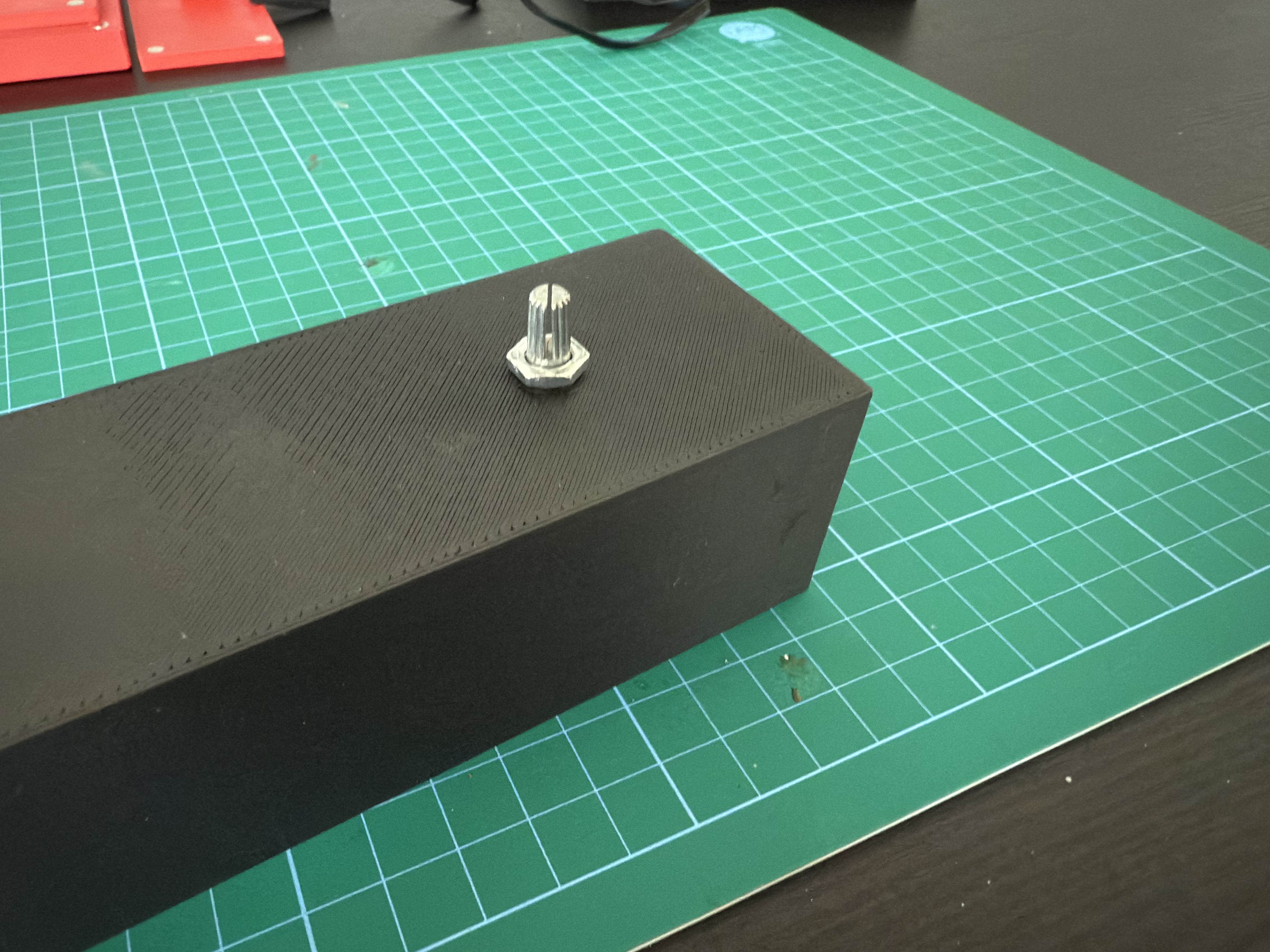
- snap the buck converter in the center slot
- place the usb c decoy in the little holder and slide into the slot

- insert the fan in the fan case, making sure to route the cable through the opening, and that the fan blows air in through the filter
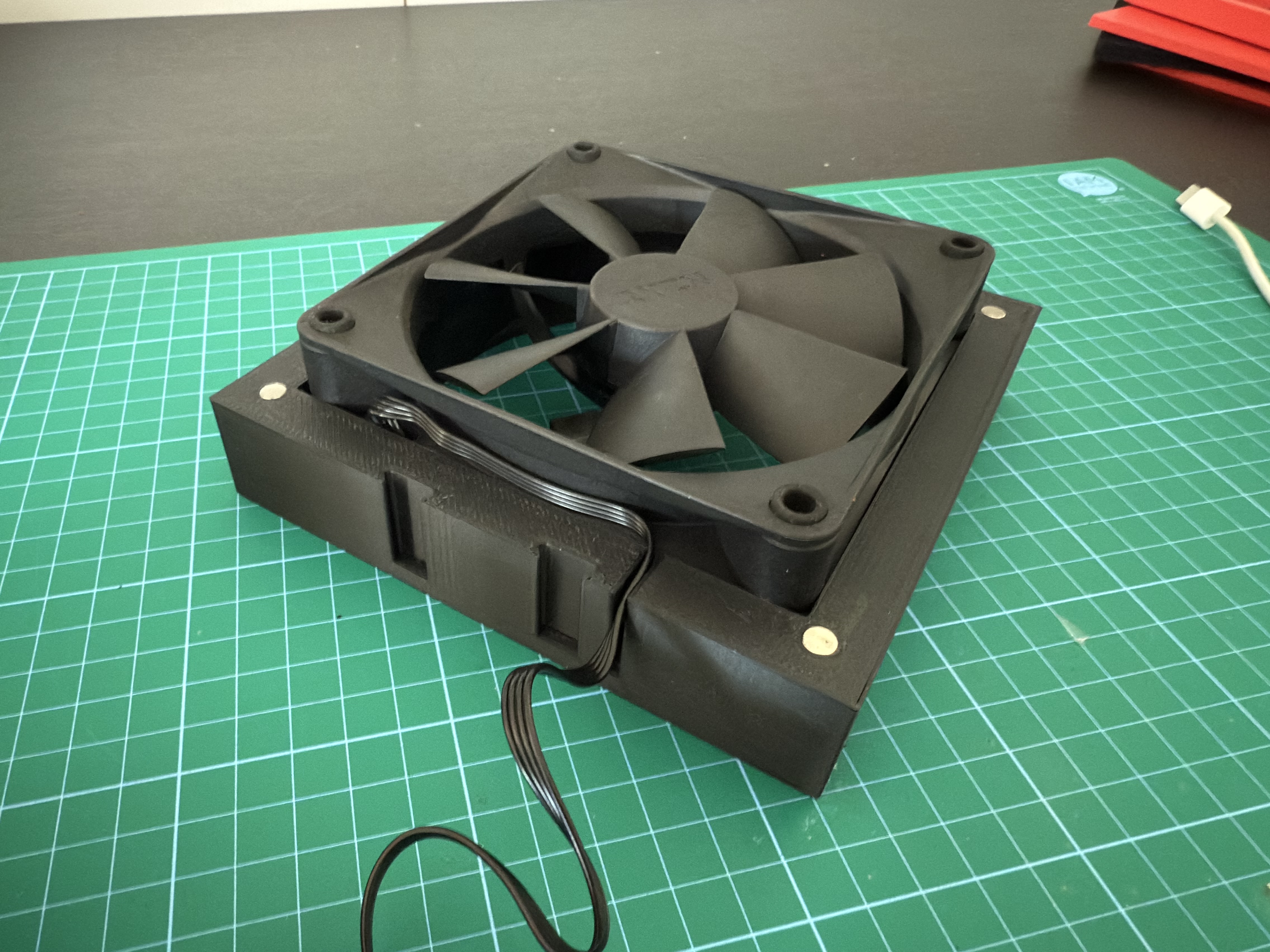
- slide the electronics box in the fan case making sure the slits align and the fan cable is correctly routed through

- connect the fan to the pwm converter header
- snap the electronics box cover on
- place a filter in the filter holder and snap the cover on
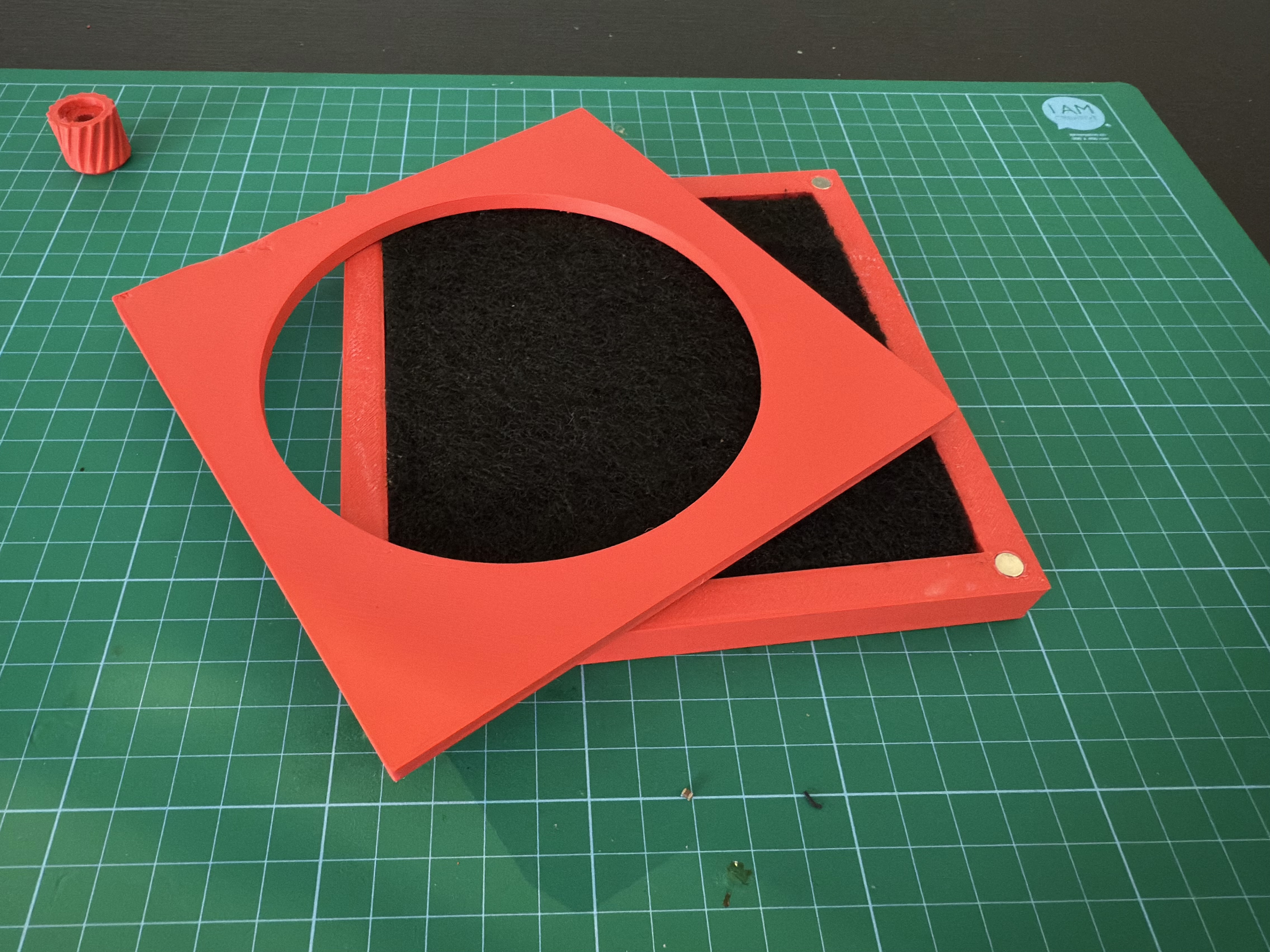
- snap the filter holder on the fan case
- press fit the knob on the potentiometer shaft
- happy soldering :)