
Stew's "Good Enough" Calibration Cross for the Qidi Plus 4
Obliczymy ostateczną cenę na podstawie wybranego pliku. Sprawdzisz ją i zaakceptujesz przed płatnością.
Zapisane na tym urządzeniu.

A simple, free, calibration cross model for the Qidi Plus 4
- Ocena
- 5 / 5
- Polubienia
- 81
- Pobrania
- 524
- Wydruki
- 9
- Wyświetlenia
- 1829
- Oceny
- 12
Aktualizacja u źródła:
Informacje o modelu
- Źródło
- Printables
- Kategoria
- Test Models
- Licencja
- Creative Commons — Attribution — Noncommercial — Share Alike
Introduction
In a sea of various calibration models, I present a very easy to use, and free, calibration cross model that will get your Qidi Plus 4 as well tuned enough for dimensional accuracy as it practicable.
Why do I say this?
Almost all modern commercial CoreXY 3D Printers, in my experience, aren't using absolutely top of the line components. If you observe carefully it can be seen that many stepper motors will have some amount of eccentricity to their motion. Whether the axles are bent or misaligned, or the pulley holes aren't perfectly centered (or straight), or the mechanism through which the belt pulley is affixed to the axle, very often there will be some degree of offset in the motion of the pulley around a theoretical true center.
This means that there is almost always some degree of “wiggle” in the motion of the pulley, resulting in an uneven distance that the belt is moved at various points of the pulley's rotation cycle. For parts whose dimensions aren't perfect multiples of the pulley circumference their printed dimensions will often have some variability depending upon what range of the pulley rotation was involved when laying down the layers of the part.
Now don't get me wrong. If a stepper and its pulley are highly eccentric, then that is a bad thing™, and should be replaced as soon as possible, but there will almost always be some small amount of eccentricity that occurs, especially on parts that have been printing for many hundreds of hours.
Summing it up, the dimensional accuracy of your parts can be both dependent upon the size of the part, and where the part is placed on the bed. That also means that beyond a certain point, expecting extreme accuracy out of budget parts is a fool's errand. Tuning dimensional accuracy to 0.01mm can become pointless because unless the target part is the exact same size as the calibration part, and placed at the exact same position, dimensions can shift.
Further, if we calibrate our motion system parameters while there is some wiggle going on, we can actually end up making things worse depending upon what factors were at play.
So what's your solution?
I propose that rather than fret about dimensional accuracy down to 0.01mm and purchasing after-market calibration models, all that's really required for the most part is a “good enough” solution that handles the general case, and chances are good that you won't need to do much more than a basic easy measurement and adjustment.
So, I've designed the following model that is easy to print. It's just a simple cross that is 110mm long on the X and Y axis.
Why 110mm?
Firstly, because that can easily be measured by the typical 150mm calipers that most users own.
Secondly, it's because 110mm is almost exactly equal to 2 rotations of each of the A and B stepper motors on the Qidi Plus 4. Stock, the Qidi Plus 4's stepper pulleys move the belts by around 38.82mm per full rotation, but over time the belts can slowly stretch and this has the effect of increasing the effective rotation distance to as much as 38.90mm
When a stepper motor turns, while other is stopped, the print head moves in a diagonal direction. The X distance travelled represents he hypotenuse of an equilateral triangle with each of the short sides equal 77.64mm, or 2 x 38.82mm.

By using a distance of 110mm for our calibration piece, we are approximating near 2 exact full turns of each A/B stepper motors and in doing so we effectively eliminate the effects of any eccentricity in the stepper motor pulleys. In this way we can be sure that when we measure the dimensions, its lengths due to filament contraction is only due to the filament, and not motion system irregularities.
How to use it?
Print out the cross in your target filament after tuning for flow rate and pressure advances. The notch on the cross should be towards the front of the printer.
IMPORTANT: Once the print is complete, and the bed has cooled down, remove the cross and then allow the cross to cool down for further 20 minutes to room temperature. This is because the print will continue to cool down internally and shrink for quite some time even after it has been removed from the print bed.
Once the part has fully cooled, measure both the distances from left to right, and front to back, and add these two values together. Ideally both measurements should be almost identical within 0.05mm. Any greater variation than this likely means that the printer's frame isn't straight and requires further investigation.

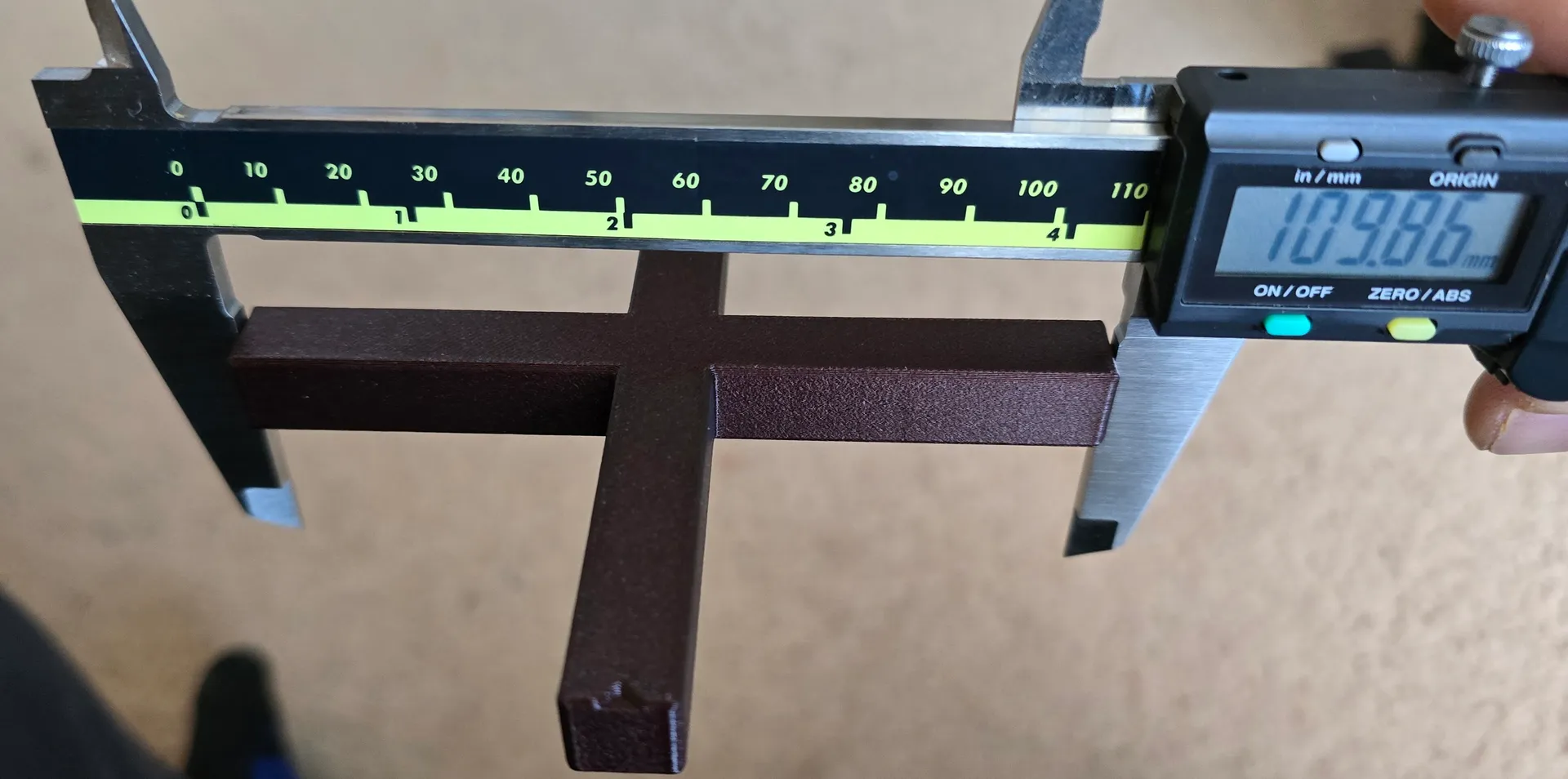
Here we see we measured 109.85 and 109.86.
After adding the two distances together (109.85 + 109.86 = 219.71mm), divide the result by 2.2. This will express the shrinkage ratio of your filament as a percentage that can be entered into the X-Y shrinkage correction factor into the filament settings in the slicer.
For our example: 219.71 / 2.2 = 99.87%. So we enter 99.87 into the Shrinkage XY Correction Factor into the filament settings.
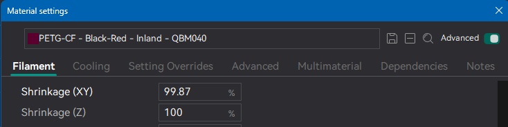
Tada! Now your filament is calibrated good enough to be confident in printing large objects and being sure that pieces will fit when they need to.