
Laser bed pin / holder tab (Parametric) (Printable & Cuttable)
Obliczymy ostateczną cenę na podstawie wybranego pliku. Sprawdzisz ją i zaakceptujesz przed płatnością.
Zapisane na tym urządzeniu.
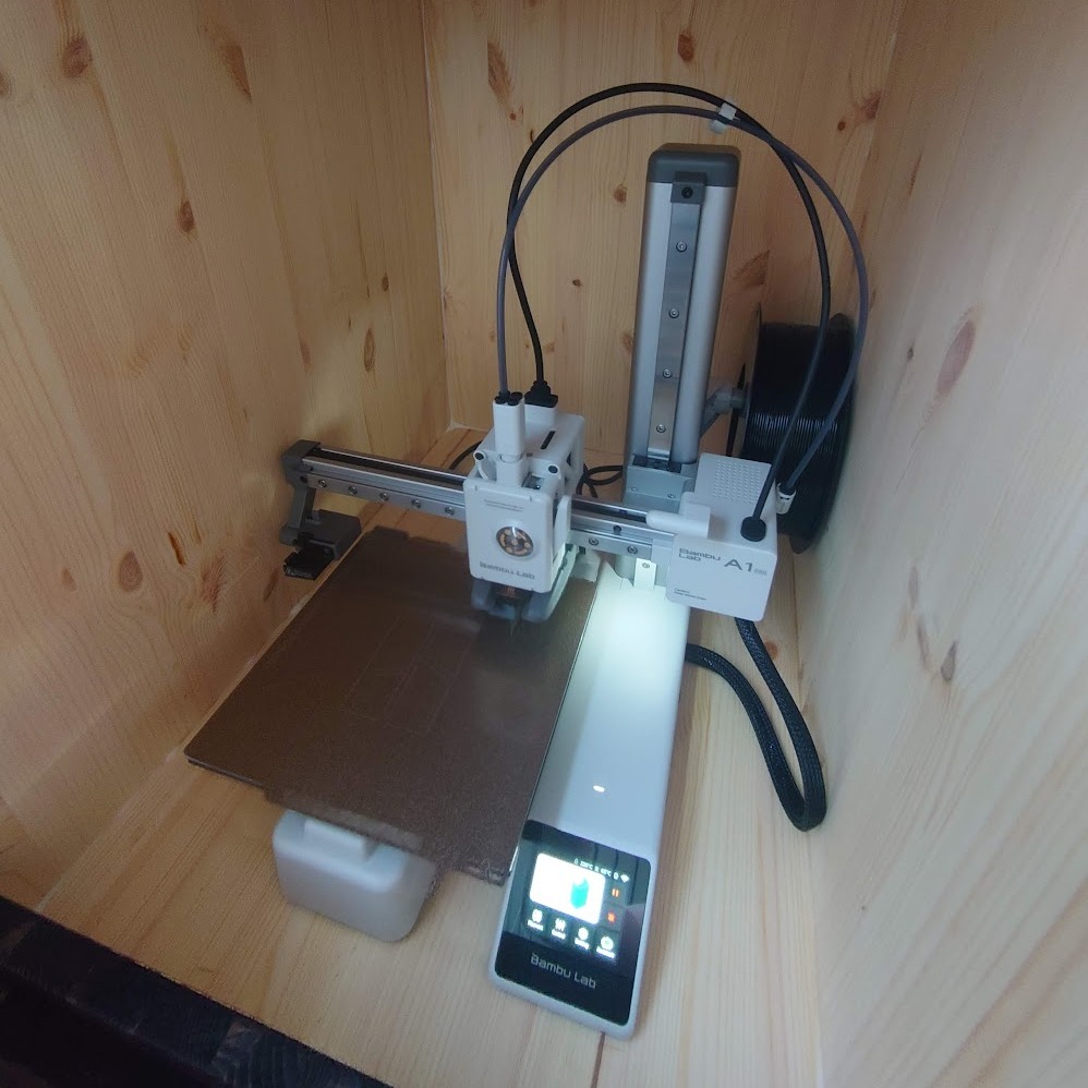
Parametric laser bed pin / holder tab designed in OpenSCAD. Held in place by friction and spring pressure.
- Ocena
- 0 / 5
- Polubienia
- 6
- Pobrania
- 33
- Wydruki
- 0
- Wyświetlenia
- 175
- Oceny
- 0
Aktualizacja u źródła:
Informacje o modelu
- Źródło
- Printables
- Kategoria
- Tools
- Licencja
- Creative Commons — Attribution
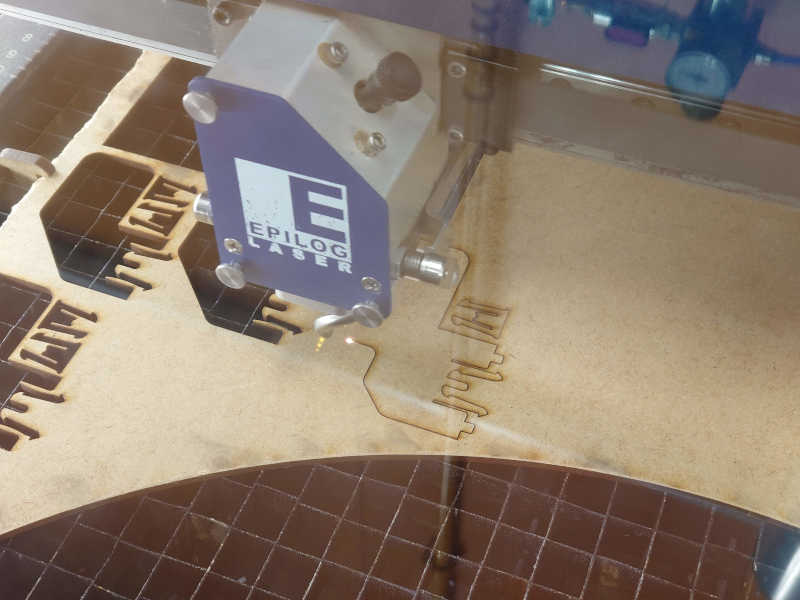
The laser tabs have been successfully used at Super Fab Lab Oulu for the Epilog Fusion M2 40 Laser for a few years now.
Originally I designed this to be laser cut, but for the FAB25 competition decided to make a parametric version in OpenSCAD including 3D-printable version.
The 3D printed version works too, athought not tested for as long.
Works best for bed grids that have an opening larger than 10 mm.
Warnings
Make sure the laser head has atleast 5 mm of clearance from the top of the cutting material
to avoid collisions.
Also the laser cuttable version is safer as you don't have to worry
cutting those with the laser.
(No idea what happens to PLA.. try at your own risk)
State
This is an improved version of my original design.
The original design was made in Fusion360.
The design is my own as is the openscad script/source file.
Printing instructions
The design is flat as it can be printed or lasercut.
The default parameters work for the 11x11 mm square grid of “Epilog Fusion M2 40 Laser”.
For anything else than the default hole width of 11 mm,
open the .scad files in OpenSCAD
and adjust the hole_width parameter.
Adjust other parameters as needed.
Press **F6** to render and then you can export STL/SCAD.
Print/cut a few to confirm fit for your laser,
and then print as many as you dare.
These will wear eventually
(atleast when the laser sweeps over them).
No post processing required, but these will be stiffer in the beginning
and after breaking in will be easy to insert and still hold really well.
Usage
Press in, pull off.
The friction should be enough to hold even warped plywood.
When the fit is good the tabs can be pulled off.
If the tabs get stuck you can twist the tabs and then pull.
Limitations
The holding force is limited by friction and very warped plywood might be too difficult to hold flat.
Although you wouldn't want to use so badly warped plywood anyhow.
Pushing the tabs all the way in will make them difficult to remove.
Also with very thick material (> 6mm with the default parameters) won't allow the teeth to grab and thus hold sufficiently.
Discussion
Considering other common designs for laser bed pins / holder tabs, this one is more flexible with the size of the hole and thus might be easier to manufacture.
I have not tested these against other designs, but they have been working well enough for Fab Lab Oulu.
This might be the earliest documented use of the original (V1) version:
https://fabacademy.org/2023/labs/oulu/students/akseli-uunila/images/week_3/laser-cutter/cutting.jpg
I am happy if other Fab Labs / Maker spaces find this useful.
For your convenience, here is the OpenSCAD script:
hole_width = 11;
hole_depth = 28;material_thickness = 4;
_flex_overlap = 1.2;
_gap = 1;
_cut_length = [4, 12];
_handle_height = 5;
_handle_width = hole_width + _handle_height * 2;
points = [
    [0,0],
    [0                                                              , _handle_height],
    [_handle_width                                                  , _handle_height],
    [_handle_width                                                  , 0],
    [_handle_width - _handle_height                                 , 0],
[_handle_width - _handle_height                                 , - material_thickness],
[_handle_width - _handle_height - _cut_length.x + _flex_overlap , - material_thickness - _cut_length.y],
[_handle_width - _handle_height - _cut_length.x + _flex_overlap , - material_thickness - _cut_length.y - _gap],

[_handle_width - _handle_height + _flex_overlap                 , - material_thickness - _gap],
[_handle_width - _handle_height + _flex_overlap                 , - material_thickness - _gap - 5],
[_handle_width - _handle_height - _cut_length.x + _flex_overlap , - material_thickness - _cut_length.y - 5],
[_handle_width - _handle_height - _cut_length.x + _flex_overlap , - material_thickness - _cut_length.y - _gap - 5],

[_handle_width - _handle_height + _flex_overlap                 , - material_thickness - _gap * 2 - 5],
[_handle_width - _handle_height + _flex_overlap                 , - material_thickness - _gap - 5 - 5 ],

[_handle_width - _handle_height -3.5                            , - hole_depth],
// Bottom middle (mirroring from here)
[_handle_height +3.5                                            , - hole_depth],

[_handle_height - _flex_overlap                                 , - material_thickness - _gap - 5 - 5 ],
[_handle_height - _flex_overlap                                 , - material_thickness - _gap * 2 - 5],

[_handle_height + _cut_length.x - _flex_overlap                 , - material_thickness - _cut_length.y - _gap - 5],
[_handle_height + _cut_length.x - _flex_overlap                 , - material_thickness - _cut_length.y - 5],
[_handle_height - _flex_overlap                                 , - material_thickness - _gap - 5],
[_handle_height - _flex_overlap                                 , - material_thickness - _gap],

[_handle_height + _cut_length.x - _flex_overlap                 , - material_thickness - _cut_length.y - _gap],
[_handle_height + _cut_length.x - _flex_overlap                 , - material_thickness - _cut_length.y],
[_handle_height                                                 , - material_thickness],

[_handle_height, 0],

];
linear_extrude(4, convexity = 6) {
difference(){
    polygon(points);
    // Fillets
    translate([0,_handle_height,0]) rotate([0,0,-90]) square_fillet(_handle_height);
    translate([_handle_width,_handle_height,0]) rotate([0,0,180]) square_fillet(_handle_height);
}
}
module square_fillet(radius, fn = 36){
    $fn = fn;
    difference(){
        translate([-0.1,-0.1,-0.1])
        square([radius+0.1,radius+0.1]);
        translate([radius,radius,-0.2])
            circle(radius);
    }
}
Updates
2025-06-09 Initial upload.