
Filament Cutter RatRig Vcore4
Obliczymy ostateczną cenę na podstawie wybranego pliku. Sprawdzisz ją i zaakceptujesz przed płatnością.
Zapisane na tym urządzeniu.

Easy-install filament cutter for VCore-4—no major disassembly or mods needed.
- Ocena
- 5 / 5
- Polubienia
- 28
- Pobrania
- 91
- Wydruki
- 1
- Wyświetlenia
- 862
- Oceny
- 1
Aktualizacja u źródła:
Informacje o modelu
- Źródło
- Printables
- Kategoria
- Other Printer Parts & Upgrades
- Licencja
- Creative Commons — Attribution
I wanted a filament cutter requiring minimal disassembly of the original toolhead. Inspired by other designs, I created this one—and it works surprisingly well.
Print settings
The main part was printed in ASA with a 0.2 mm layer height, 4 walls, and 25% grid infill.
While ASA was chosen for its superior heat resistance, the PETG prototype performed well during the printing of ASA components for the filament cutter. Nevertheless, it would likely deform under prolonged exposure to elevated chamber temperatures.
All parts should already be oriented correctly when imported. All overhands can be printed without supports, just check the orientation. On Lever I used a little support on the spring holder.
Before you begin
The 16 mm bolts and bolt spacers were used simply because they were the only ones available at the time. They're optional, and you can use different bolt sizes if preferred. Note that the filament cutter adds 5 mm to the overall assembly thickness.
What you need
Print list
- 1x Lever
- 1x Spacer_Orbiter
- 1x Spacer_Ventilator
- 2x Spacer_Bolt - optional (see above)
Parts list
- 4x M3x40 bolt (DIN912)
- 2x M3x16 bolt (DIN912) - optional (see above)
- 1x Blade #4
- 1x PTFE tube 17.7mm
- 1x PTFE tube 6.8mm
- 1x Pen spring (~OD 4,3mm, L28mm)
Pre-assembly
- Cut the two PTFE tube pieces to their respective lengths.
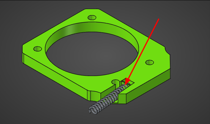
- Insert the pen spring into Spacer_ventilator.
- Insert blade #4 into Lever (use pliers to push it in).
- Tip: Apply a small amount of glue if you're concerned it might fall out.
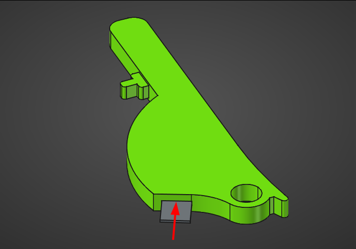
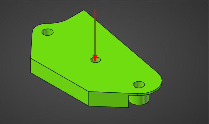
- Punch out the hole on Spacer_Orbiter, and clean it if needed.
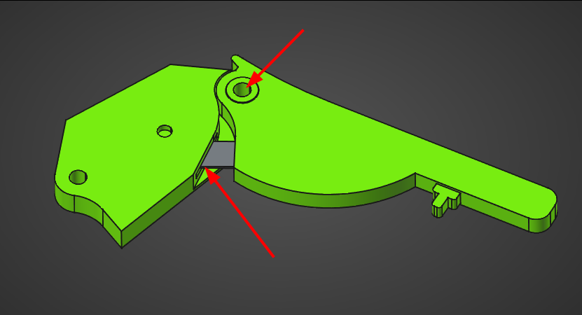
- Assemble the Lever (with blade inserted) and the Spacer_Orbiter
- Tip: First align the blade with the opening, then slide the Lever onto the spacer at an angle.
Assembly
- Unscrew 2x M3x8 bolts securing the Orbiter extruder to the mounting plate.
- Unscrew the bolt connecting Orbiter to the umbilical & toolboard vertical holder.
- Gently move the Orbiter aside.
- Pull out the PTFE tube from the hotend (use pliers if needed).
- Unscrew 4× M3x35 bolts holding the vertical holder and fan grill.
- Move the vertical holder and fan grill to the side.
- Place Spacer_Fan (with spring) onto the fan.
- Reposition the vertical holder and grill over it, then secure everything using 4× M3x40 bolts.
- Push the long PTFE tube into the hotend until it's flush.
- Place the Spacer_Orbiter (with Lever) over the hotend mounting holes.
- Push the short PTFE tube into the Orbiter extruder until it's flush.
- Position the Orbiter extruder on top of the spacer.
- Use either your own bolts or place Spacer_Bolt on each side and secure with 2× M3x16 bolts.
- Reattach the Orbiter to the vertical holder using original bolt.
- Press the pen spring onto the Lever’s spring holder.
- Test the cutter :)
End result
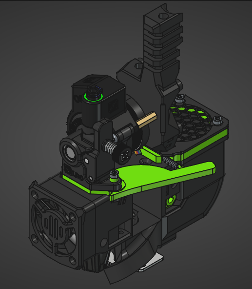
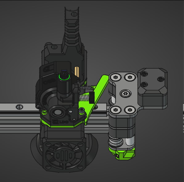
The cutter arm pushes against the printer's built-in 3D printed X gantry end stop to perform cutting, eliminating the need for extra printed components.
On my VCore 4 (300 mm) this mean, the toolhead parks at X336 before Lever is pressed and performs the cut at X357.
Custom Code
Since the design doesn't involve any servo motors or complex actuation, creating custom G-code is straightforward. All motion is mechanical, so you can integrate the cutting routine directly into your existing toolchanging or filament change macros.
If you're using a V-Core-4 and made it this far, you're probably more than capable of writing a simple, effective G-code routine tailored to your setup.