
FMController (DISCONTINUED)
Obliczymy ostateczną cenę na podstawie wybranego pliku. Sprawdzisz ją i zaakceptujesz przed płatnością.
Zapisane na tym urządzeniu.

This controller transforms your CMF Phone 2 into a portable console, while keeping it slim enough to fit in your pocket.
- Ocena
- 0 / 5
- Polubienia
- 152
- Pobrania
- 79
- Wydruki
- 0
- Wyświetlenia
- 4644
- Oceny
- 0
Aktualizacja u źródła:
Informacje o modelu
- Źródło
- Printables
- Kategoria
- Video Games
- Licencja
- Creative Commons — Attribution — Share Alike
THIS DESIGN IS DISCONTINUED AND HASN'T BEEN TESTED. IT PROBABLY ISN'T FUNCTIONAL SO I WOULDN'T ADVICE BUILDING IT.
INTRODUCTION
The FMC (Flat Mobile Controller) attaches to your phone case and slides under the phone when needed, allowing you to play your favorite games with the comfort of a controller anywhere. When not in use, it stays compact enough to keep the whole setup in your pocket.
The different positions of the controller are secured using the accessory point cover of the CMF phone 2. Completely unscrewing the accessory point allows you to enjoy a fully standalone Bluetooth controller.
Despite being very thin (~12mm), it includes all the features of a full-size controller :
- 11 buttons with silent mechanical switches
- A D-pad
- 2 dual-axis joysticks
- 2 analog Hall effect triggers or 2 mechanical switches triggers
The 4 buttons on the back of the controller are the sticks buttons and the bumpers.
The controller is powered by a Seeed Studio XIAO ESP32-S3 Plus (TinyPICO NANO version won't be updated anymore) supplied by a 500mah LiPo battery and is designed to work with the ESP32-BLE-Gamepad library. It also features a custom-made PCB!
HARDWARE
This list includes only the components for the basic version of the controller. For mods or alternative versions, refer to their hardware section in their dedicated assembly guides (see "Other" file section).
Available mods/ alternative versions:
- Digital triggers
- No PCB
STICKS:
2× Nintendo new 3ds joysticks that look like this (there are different types of 3ds sticks)
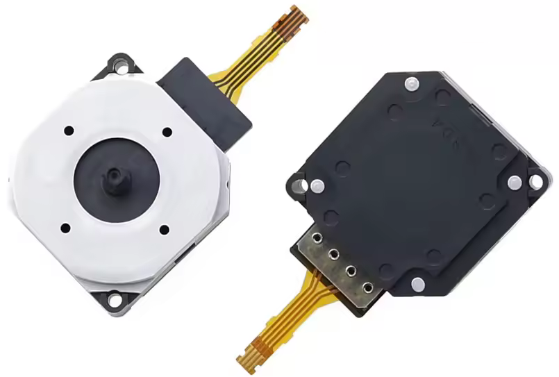
4× Nintendo 3DS joystick screws (8mm x 1.5mm x 2.5mm)
2× FFP FPC connectors 4pins 0.5mm pitch
BUTTONS:
15x 6x6x3.5mm 2 pins (silent) mouse switches (ex: HUANO Mute Button 6*6*3.5mm; Kailh Mini 6.2mm Silent Micro Switches)
TRIGGERS:
2× SS49E Hall effect sensors
2× round 6x3mm magnets
2× springs (20×0.6×5mm)
ACCESSORY POINT:
1× M2.5 18.35mm threaded rod (buy a screw and cut it) or a M2.5 screw with external hexagonal head (in that case no nut needed)
1× M2.5 nut
ELECTRONICS AND PCB:
1× 603030 LiPo battery (30x30x6mm)
2× × 200 kΩ resistors (0805) and 1 × 100 nF capacitor (0805) (optional, only needed if you want battery monitoring)
1× Seeed Studio XIAO ESP32-S3 Plus and an antenna
8× BAT54C diodes
1× USB-C female 16 pin port
2× 5kΩ resistors (0805)
1× SS-12D00 2mm shaft slide switch
5× M2 3mm screws (max head height: 1.8mm)
The custom PCB
OTHER:
9× M2 4mm countersunk screws
All the 3D-Printed parts
A few wires, some glue and a soldering iron
It is recommended to completely read the assembly process before buying anything.
TinyPICO NANO version will not receive updates anymore. All the files can still be found in the other files section.
NEEDED UPDATES :
Body improvement for clean surfaces in joystick
Compatibility with more switches
Ergonomic improvements for different hand sizes
Dropped ideas
- Adding gyroscope support: gyro support would mean major changes to the pcb+ code modification and per-user calibration as it is not possible to send the gyro data to the phone while having 2 joysticks and 2 analog triggers (see more here) (possible but complicated)
Feel free to share your ideas or feedback. I'll be happy to hear them!
PRINTING
All models are oriented.
- Main body: Choose only one version (depends on the controller you choose and if you want the logo). Logo version are only for multicolor prints (extruded logo this small doesn't look good). Print with supports.
- Triggers: Choose only one version, analogic or digital. I you want digital version you also have to print the 2 spacers.
-Backplate: first layer needs to be perfect as the walls behind the joysticks are only one layer (cosmetic only). Be careful when removing the backplate from the plate.

ASSEMBLY FOR XIAO ESP32-S3 Plus
The old assembly for the TinyPico NANO version can be downloaded under "other files"
Note: "Switches" refer to the mechanical switches; "buttons" refer to the 3D-printed button caps.
I. Soldering the PCB
1. Off-board buttons and SS49E
FOR DIGITAL TRIGGERS REFER TO THEIR SPECIFIC GUIDE FOR THIS SECTION
Solder wires to the 4 off-board switches:
- 2 switches: each with two 8mm long wires
- 2 switches: one wire of 31mm, one wire of 28mm

Cut all pins on each SS49E to 2mm long.
Solder 6 wires to the 2 SS49E:
First SS49E:
- OUT: 13mm long wire
- GND: 14mm long wire
- VDD: 14mm long wire
Second SS49E:
- OUT: 37mm long wire
- GND: 36mm long wire
- VDD: 35mm long wire

2. Front of the PCB
FOR DIGITAL TRIGGERS REFER TO THEIR SPECIFIC GUIDE FOR THIS SECTION
Solder the following components to the front side of the PCB:
- 7 BAT54C
- 2 FFP FPC connectors
- XIAO ESP32-S3 Plus
- 2 SS49E (⚠ long-wire SS49E to the left short-wire SS49E to the right)
- Lipo battery
- USB-C port
- 2 5kΩ resistors under the USB-C port
- 2 off-board switches with short wires
- 2 200kΩ resistors and 1 100nF capacitor (on the bottom left of the PCB) (optional, only for battery monitoring)

3. Back of the PCB
- Connect the battery, D+ and D- CMS pads on the controller to their respective pads on the PCB using wires.

Solder the following components to the back side of the PCB:
- 11 switches
- 2 off-boards switches with long wires
- SS-12D00 slide switch

Cut all component pins/wires (both front and back) to a maximum height of 2mm above the PCB surface.
Your PCB assembly should now be complete.

II. Mounting the PCB
1. Preparing the controller body
FOR DIGITAL TRIGGERS REFER TO THEIR SPECIFIC GUIDE FOR THIS SECTION
- Mount the 2 joysticks tops as shown in this video
- Place the A, B, X, Y, Home, +, - buttons and the power switch cap in the controller body

2. Placing the PCB
- Install the antenna on the Seeed Studio XIAO ESP32-S3 Plus as explained in their wiki :
“Put one side of the antenna connector into the connector block first, then press down a little on the other side, and the antenna will be installed.”

- Connect the joysticks bodies to the FFP FPC connectors on the PCB with their ribbon cable. The joystick shafts should face the front side of the PCB.

FOR DIGITAL TRIGGERS REFER TO THEIR SPECIFIC GUIDE FOR THIS SECTION
- Align the joystick tops with the joystick bodies and ensure the power switch cap aligns with the slide switch on the PCB.
- Place the bumper switches in the controller body
- Route the antenna wire through its channel, underneath the wires of the right SS49E
- Place the PCB in the controller body (⚠ align the power slide switch)
- Place the SS49E, the sticks switches and the joysticks in the body (⚠ align the joysticks bodies and top)

- Secure the PCB with five M2 3mm screws and joysticks with their 4 screws.
III. Triggers, rear buttons and backplate
1. Glue the magnets into the holes furthest from the hinge on both triggers.
2. Triggers and buttons placement
- Insert the triggers in the body (⚠ left and right triggers are different)
- Place the bumpers and sticks buttons in the body

3. Align the antenna with the recess in the backplate, then secure the backplate in place using 7 M2 4mm countersunk screws.
4. Add the triggers shaft:
You can watch the shaft assembly here.
- Cut ~2cm of filament and thread it through the backplate, trigger, and body.
- Use your printer nozzle (180°C for PLA) to melt one end, creating a rivet.
- Trim the excess, leaving a few millimeters exposed, then melt the other end.
5. Screw the body front face with the 2 remaining M2 4mm countersunk screws
IV.Accessory point cover
1. Cut a M2.5 threaded rod or screw to ~18.35mm (you may want to file the tip a little to make screwing easier).
2. Glue the M2.5 nut or the head of the hexagonal screw in the 3d printed accessory point cover.
2.5. Screw the threaded rod in the nut.

Your FMController assembly should now be complete.
Code
You can now add the code to your FMController! Download FMController-Code_XIAO_ESP32-S3_Plus.zip from the Other Files section. The code may require adjustments, as it has not been tested under real conditions yet.
Upload it to your controller by following the installation instructions provided in the ESP32-BLE-Gamepad library documentation.
After installing the ESP32 board package in the Arduino IDE, select XIAO_ESP32S3 as your board and upload the code.
Once your code is loaded,
1. Open the Serial Monitor in the Arduino IDE and set the baud rate to 115200.

2. Unplug the controller from your computer.
3. Turn off battery power (slide the switch to the right position).
4. Press and hold the A button and the D-pad Up button.
5. While holding them, reconnect the controller to your computer via USB.
You should now be in calibration mode. Follow the on-screen instructions in the Serial Monitor. Once your controller is fully configured, you won't need to repeat the calibration (unless you make hardware changes or drift starts appearing).
Additional information (please read)
Charging:
To charge the device, the power switch on the controller must be in the ON position. If the switch is OFF, the battery is completely disconnected from the ESP and cannot charge.
If the power switch is OFF, you can still use the controller while plugged in but the connection will only via Bluetooth.
Battery LED operation:
1. When XIAO ESP32S3 is not connected to the battery, the red light comes on when the Type-C cable is connected and goes off after 30 seconds.
2. The red light flashes when the battery is connected and the Type-C cable is connected for charging.
3. When connecting Type-C to charge the battery fully, the red light turns off.
CONNECTED PINS (ONLY XIAO ESP32-S3 Plus)
TinyPico NANO version can be found in the “GUIDE FOR TINY PICO NANO ASSEMBLY” under other files.
Buttons Matrix | ||||
| Col0 (D17) | Col1( D18) | Col2 (D3) | Col3 (D7) |
Row0 (D12) | LB | LS | RB | RS |
Row1 (D13) | Select | Home | Start | Unconnected |
Row2 (D19) | A | B | X | Y |
Row3 (D14) | Down | Right | Up | Left |
Sticks | ||
| Axis | Pin |
Left Stick | X | A1 |
| Y | A0 |
Right Stick | X | A8 |
| Y | A9 |
Triggers | |
| Pin |
Left Trigger | A5 |
Right Trigger | A10 |

Changelog
07/08/25: added no pcb version (models & assembly); updated PCB and body for minor improvements; updated source files
07/07/25: updated hardware sections
07/06/25: added Additional information section + updated test section
07/04/25: new easier (clean) esp's usb to pcb connection; added hole in body to see battery charging indicator; updated instructions (main & digital) accordingly; archived tinypico nano version (will not receive updates)
06/24/25: updated triggers assembly guide for new calibration process
06/23/25: added calibration process in XIAO ESP32-S3 Plus code (+ updated instructions accordingly)
06/22/25: updated XIAO ESP32-S3 Plus code for battery reading; corrected wrong stick pinout on PCB
06/21/25: updated PCB to allow battery reading; updated main body for the new PCB; updated source
06/19/25: updated print recommendations and accessory point cover instructions
06/18/25: added a digital triggers mod (models + assembly + code modification); corrected small schematic issue in pcb; updated source files
06/16/25: updated source files
06/15/25: updated assembly for XIAO ESP32-S3 Plus. Old assembly for tiny pico nano can be found in other files; updated PCB silkscreen; added antenna space for esp32-S3 version; updated code for XIAO ESP32-S3 Plus.
06/14/25: added code for tiny pico nano version (not tested in real condition); added Seeed Studio XIAO ESP32-S3 Plus version
06/13/25: changed license; power switch design modification; added print orientation; added version without logo; added step and kicad source files "FMController v69.zip"; updated unconnected buttons on PCB; added connected pins
06/12/25: fixed joysticks position
06/11/25: fixed tolerances of home + - buttons and dpad; ergonomic adjustement
06/10/25: fixed a b x y and joysticks tolerances
Tests:
- Buttons tolerances ✅ (not tested with switches)
- Joysticks ✅
- PCB ❌
- Switches ❌
- Trigger
- SS49E ✅
- Spring ❌
- Magnet ✅
- Tolerances ✅
- Shaft ✅
- Cover ❌
- Slider ✅
- Print orientation + strength on phone ❌
- Dpad tolerances ✅
- Accessory point cover ❌
- Rear buttons tolerances ✅
- Backplate tolerances ✅
- Digital triggers upgrade ❌
