
Versatile filament + Qidi dry-box spool mounting arm
Obliczymy ostateczną cenę na podstawie wybranego pliku. Sprawdzisz ją i zaakceptujesz przed płatnością.
Zapisane na tym urządzeniu.

A versatile filament + Qidi dry-box spool mounting arm allowing for various positioning arrangements
- Ocena
- 5 / 5
- Polubienia
- 21
- Pobrania
- 174
- Wydruki
- 0
- Wyświetlenia
- 1409
- Oceny
- 2
Aktualizacja u źródła:
Informacje o modelu
- Źródło
- Printables
- Kategoria
- Other Printer Parts & Upgrades
- Licencja
- Creative Commons — Attribution — Noncommercial — Share Alike
Introduction
A reasonably easy to print filament spool holder system for the Qidi Plus 4
This allows for the mounting of bare spools and the Qidi Dry Box. It re-uses the stock spool holder spindle that ships with the printer. Spools can be easily re-oriented for feeding into the side filament entry hole, or hanging over the build plate area to allow for direct feeding into the tool-head, which is useful for TPU or any other flexible filaments.
Also provided is a slide on disk that snugly fits onto the spindle, and is clipped into the place with the stock twist-clip. This prevents spools even with very large central openings from falling off the spool holder as has been known to happen.
A stock arm holder base attaches to the existing mounting location of the original arm holder. This unit is significantly stronger and sturdier than the stock piece, and provides an octagonal shaped hole that allows for the main spool arm to be rotated in any of 8 directions.
Also provided is a small twisted height extender piece. This is intended to slide in between the arm and the base and tilts and orients the arm a little better above the main printing area when bypassing the side filament entry point. This model also introduces a slight tilt. When using the Qidi dry-box, it can help to rotate this piece such that it leans the dry-box back, which improves the filament exit path from the drybox. If using a bare spool, it can help to rotate this piece to lean the spool more over the build-plate for a more direct path into the tool-head.
Printing the parts
While the parts are fairly easy to print, printing them in certain orientations makes them stronger and more fit for the stresses of the role they serve. I printed all parts with a 0.4mm nozzle with a 0.2mm layer height.
NOTE! This model has multiple parts that slide together very closely. Everything is tuned with 0.2mm clearances will I found allows for the best clearance to still allow for parts to slide smoothly together, but with some slight stiffness, which prevent the assembled pieces from wobbling.
As a result of this, be sure to calibrate your filament flow rates for the filaments that you will use. If you over-extrude, then the parts will fit together poorly, if at all. This is very important for this particular model.
Spool Holder Disc
This is the easiest to print, with the flat base against the build plate. It can be printed in PLA, and I advise using concentric pattern for the base and top surfaces, as this will provide the least friction against spools rubbing on it. The main strength settings I used are provided in the image below

Holder Base
This is the piece that will bear the most stresses. I highly recommend printing this in PET, ABS, ASA, PA, or PC, preferably with a composite fiber, such as CF or GF.
Do NOT use PLA, and be careful with PETG. This part bears load and sits against the hot chamber and will need to cope with temperatures up to 70C while being loaded.
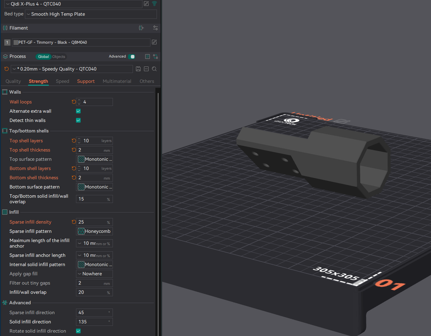
It is very strongly recommended to print this piece in the following orientation. No supports are required. Use 4 walls, and 25% honeycomb, gyroid, or 3DHoneycomb infill.
Main Spool Arm
This is the big one. I also recommend the same strength settings as for the holder base above.
This piece also requires supports. Here I wholly recommend using normal supports, not trees, as the regular supports will be easier to remove. I'll provide an image below of the best orientation on the plate, along with the support settings I use. When printed with these settings, the supports should snap away easily leaving a clean surface, and for the supports in the central circular section, this can typically be easily pushed out from above, and then pulling them through from the bottom of the piece.

Twisted Extender Piece
This piece is a little trickier because there's no one orientation that works best. I recommend printing in the following orientation, but also setting up a height range modifier to provide the best strength for the transitional area between the male and female portions of the piece. Use 100% infill between the heights of 41 and 48mm, and this will ensure that the part is strongest within this critical area of the piece.
Use the same strength and support settings from the above two pieces as well.

Support the creator
Enjoying my work? Maybe buy me a coffee! https://ko-fi.com/stew675