
Suzuki Jimny JB74 modular phone mount (parametric)
Obliczymy ostateczną cenę na podstawie wybranego pliku. Sprawdzisz ją i zaakceptujesz przed płatnością.
Zapisane na tym urządzeniu.
Parametric phone mount for the Suzuki Jimny JB74.
- Ocena
- 0 / 5
- Polubienia
- 5
- Pobrania
- 134
- Wydruki
- 0
- Wyświetlenia
- 678
- Oceny
- 0
Aktualizacja u źródła:
Informacje o modelu
- Źródło
- Printables
- Kategoria
- Automotive
- Licencja
- Creative Commons — Attribution — Noncommercial
This phone mount for the Suzuki Jimny JB74 is part of my ModMount (Modular Mount) system. This system comprises mounts, connectors and device holders.
The mount is designed to fit using one of the existing fixture holes along the dash trim. The connector, which angles the device at 15 degrees, also rotates to ensure the optimal viewing angle.
The phone cradle is a parametric Autodesk Fusion component, allowing it to be tailored to your specific phone model.
I've included the STL for the cradle I created using Fusion for my Pixel 8A (in a Spigen clear soft case), so the cradle design can be reviewed in the 3D viewer.
Additional hardware required
| Quantity | Item |
| 2 | M4 heat set inserts |
| 1 | M8 x 25 Socket Head Cap Screw |
| 1 | M4 x 16 Countersunk Screw |
| 1 | M4 x 12 Countersunk Screw |
Cradle customisation
The phone cradle dimensions can be adjusted by changing the applicable parameters using Autodesk Fusion (a free license is available for makers).
Take accurate measurements of the features below in mm, ideally using digital callipers if available, and modify the component parameters as necessary.
** Ensure the measurements are taken at the widest points referenced in the image below, especially if additional bumpers have been added for example.

| Parameter | Notes | |
| A | phone_width | |
| B | phone_thickness | |
| C | phone_height_to_switch | Height to the bottom of the lowest side switch. The side wall height is set to 7mm below this measurement. |
| phone_caddy_clearance | Added to each of the 3 parameters above to give the phone clearance inside the caddy. Default value 0.4mm |
Printing
I used the material and settings shown below
- ASA
- 0.16 mm layer height
- 6 walls (to allow for the heat set inserts)
- 25% Infill
- Supports - used for phone cradle only
- Brim - used for the phone cradle only
Other filament types may be suitable depending on local conditions, as the inside of a vehicle can get very hot in sunny weather.
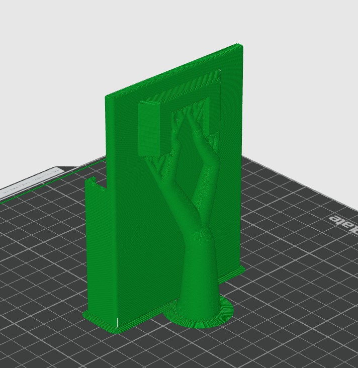
No supports are needed for the mount and connector if they are printed in the orientation shown in the image below.

I produced the cradle separately, setting the base on the build plate and print using a small brim and supports.
** Please note
3D printed parts shrink slightly as they cool. So even though you may have taken accurate measurements, your phone may be a tight fit in the cradle.
I would suggest printing a test part first of just the bottom 25mm of the cradle, using draft settings. Then test the fit or confirm measurements before printing the final version, making adjustments to the model parameters if necessary.
Assembly and installation
Install the two M4 inserts using a soldering iron.
Be careful to secure the printed parts in a safe stable position when doing this due to their shapes.
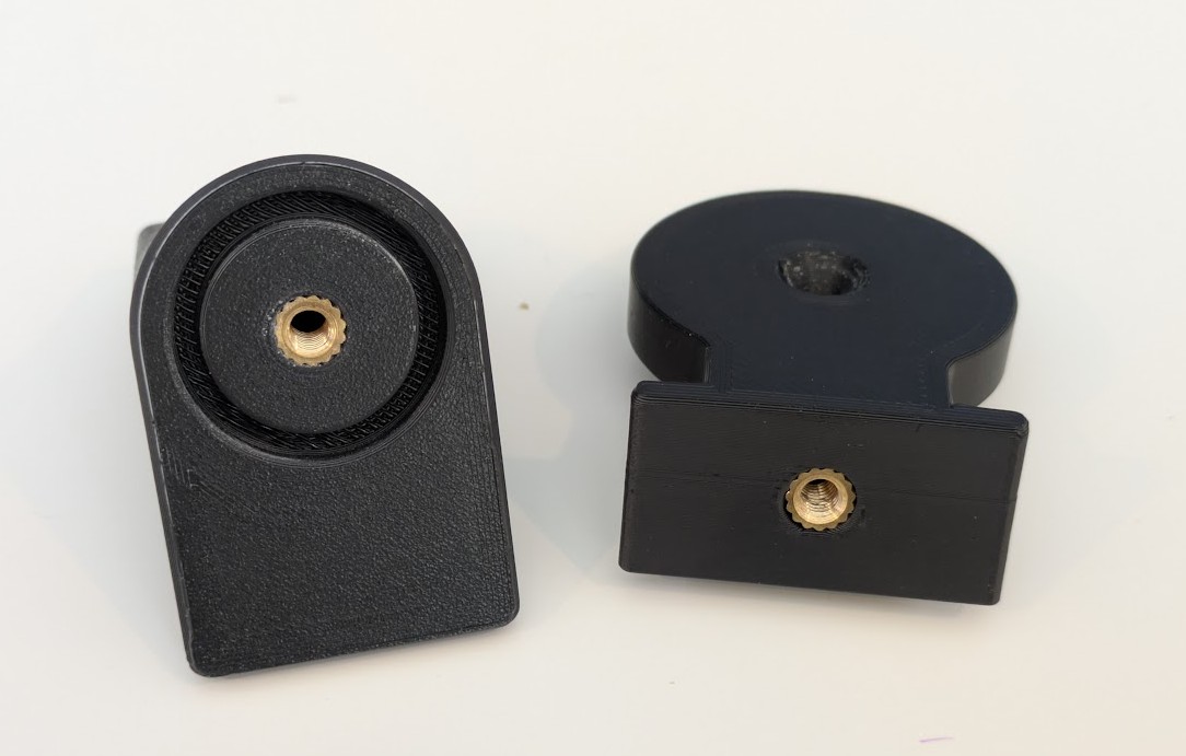
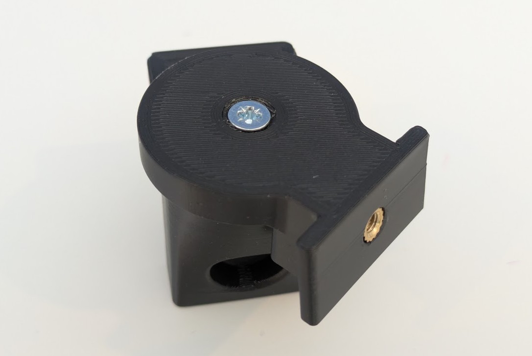
Fit the 15 degree connector to the mount using the M4 x 16 countersunk screw.
Tighten it gradually until the connector will stay in position, but is still able to be rotated without too much force.
Now to the vehicle.
Choose a suitable mounting position and remove the part covering the fixing hole. These look like a socket head cap screw, but the standard part fitted to the vehicle is a dummy and actually made of some type of rubber. They can be unscrewed by turning anticlockwise with the ends of your fingers, or using a 6mm allen key.

The exposed threaded fitting.

Install the mount securely with the M8 x 25 socket head cap screw and a 6mm allen key.

The phone cradle can now be fitted over the connector and secured using the M4 x 12 countersunk screw.

All done.

The centre hole in the base of the cradle is for the USB cable.
There are also two unused countersunk holes to the outside of the base to allow a future module to be added with a captive USB connector, for automatic phone connection.

Warning
Please ensure that when fitted to your vehicle, the phone mount doesn't
- interfere with any vehicle controls
- block the path of any safety features such as air bags etc.
- create a hazard in the event of a collision
Support
If you've found this design useful, please consider supporting my work with a coffee.
https://coff.ee/reedx