
Qidi Plus 4 Chamber Temperature Probe Mount
Obliczymy ostateczną cenę na podstawie wybranego pliku. Sprawdzisz ją i zaakceptujesz przed płatnością.
Zapisane na tym urządzeniu.

A mount to relocate the chamber temperature probe for more accurate temperature reporting
- Ocena
- 4,667 / 5
- Polubienia
- 90
- Pobrania
- 658
- Wydruki
- 10
- Wyświetlenia
- 3183
- Oceny
- 12
Aktualizacja u źródła:
Informacje o modelu
- Źródło
- Printables
- Kategoria
- Other Printer Parts & Upgrades
- Licencja
- Creative Commons — Attribution — Noncommercial — Share Alike
This model and associated optional configurations are the result of months of trial and error work to improve the chamber heater behaviour of the Qidi Plus 4.
The stock chamber thermal probe is located under the frame rail to the back-right of the printer chamber. It is shown here circled in blue.
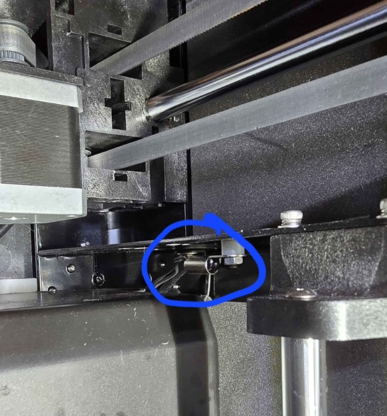
Unfortunately this location is near where drafts exit the mainboard chamber. Additionally, it is not adequately thermally isolated from the metal frame of the printer, and that means that the thermal probe in its stock location can read anywhere from 5-15C below the actual chamber temperature.
Further, when the chamber heater is on, the forced air outflow from the chamber heater blows hot air directly over the probe, so when the printer is trying to warm the chamber up the probe will read hot, even though the chamber may not be up to temperature. This results in chamber temperatures that can oscillate between too cold and too hot in a cycling fashion, which isn't ideal.
A full investigation of these issues are discussed in more detail here.
We can address these issues by moving the sensor to this location using this mount:
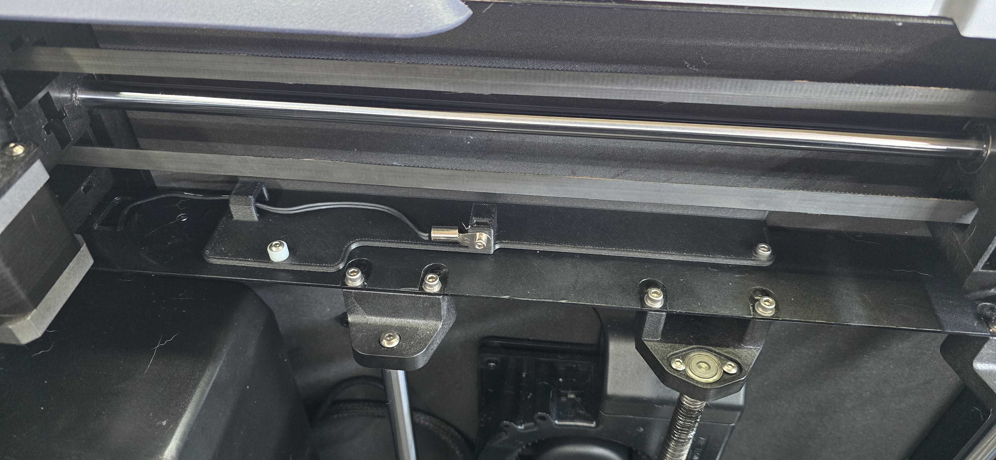
Note that typically there's a fair amount of additional length for the thermal probe cable, however it is usually cable-tied to other cables in the mainboard chamber. If you find that you don't have sufficient cable length for this mod, remove the rear panel and cut the cable tie holding the thermal probe to free it, and re-tie the cable bundle again.
Moving the probe to this position takes the sensor away from the direct blast of hot air coming from the chamber heater while it is running, as well as providing for better thermal isolation from the main printer frame. An M3 square nut is placed into the probe mount that the stock metal sensor mount eyelet is bolted onto using an M3x8mm bolt.
The main mount is then attached to the frame via some of the mount point holes that are already pre-drilled into the frame. An M3x8mm bolt works for the right-side of the mount in the photo, and the stock bolt and nut works for the left side.
I personally like to put the white nylon washer in the location shown so it doesn't get lost, but otherwise it is not necessary to be there. The cable is run through the cable guide to prevent it from interfering with the motion system and runs down to the main-board chamber via the cut-out in the frame to the right of the rear stepper motor.
Printing Tips
A 0.2mm layer-height is ideal, and printed in any filament that is tolerant of 80C+ temperatures. I used ABS-GF25 for the model in the photo myself. No supports are required.
RECOMMENDED (BUT OPTIONAL) CONFIGURATION CHANGES
A better Chamber Heater Configuration (optional)
After installation, it is recommended to make the following configuration change in your printer.cfg file
[duplicate_pin_override]
pins: U_1:PA1[heater_generic chamber]
heater_pin:U_1: PC8
max_power: 0.6
pwm_cycle_time: 0.135335
control: pid
smooth_time: 30
pid_Kp: 60
pid_Ki: 0.12
pid_Kd: 0
min_temp: -100
max_temp: 85
sensor_type:NTC 100K MGB18-104F39050L32
sensor_pin:U_1:PA1
Note the addition of the smooth_time line, and the changes to pid_Kp, pid_Ki, and pid_Kd.
This PID change is much more appropriate for where the chamber temperature sensor is now located with this model. It provides for a much more steady control of the chamber heater that places a strong focus on keeping the chamber heater's power level as smooth as possible to minimise rapid cycling of the heater coils which can have an adverse impact on print quality depending on the quality of mains power delivery to the printer.
A Klipper heater algorithm modification (optional)
In addition to the above configuration change, you may also like to over-write /home/mks/klipper/klippy/extras/heaters.py with the contents of one of the following files.
Be sure to back up the original version of that file first.
- Firmware 1.4.2 full version of heaters.py -OR- Context patch file for 1.4.2
- Firmware 1.4.3 full version of heaters.py -OR- Context patch file for 1.4.3
- Firmware 1.6.0 full version of heaters.py -OR- Context patch file for 1.6.0
I'm not going to explain how to do this here as if you're unsure of what to do already just from that description alone, then I don't want to encourage you to do something that modifies your Klipper installation.
After replacing the heaters.py file for your specific firmware version, type sync on the printer's ssh console, and then turn the printer off and on again to activate the new file.
This new file changes the temperatures fed into a heater's PID algorithm to be the temperature value smoothed over the configured smooth_time period. This is only applied for heaters where smooth_time is defined to be greater than 1s, which means that the hotend's behaviour will be unaffected.
This has the effect of further smoothing out the power operation of the chamber heater to provide for a very stable chamber temperature which will in turn have a positive impact on print quality.
A better bed heater PID configuration (optional)
If you've applied the above, then you may also consider the following bed heater configuration changes which applies the same heater smoothing behaviour to the print bed heater, which very strongly smooths out the power feed to the print bed, also limiting power spikes on the printer's power supply:
[heater_bed]
heater_pin: U_1:PB10
sensor_type:NTC 100K MGB18-104F39050L32
sensor_pin:U_1: PA0
max_power: 1.0
control: pid
smooth_time: 5
pid_Kp: 100
pid_Ki: 0.6
pid_Kd: 0
pwm_cycle_time: 0.001
min_temp: -60
max_temp: 125
Support the creator
Enjoying my work? Maybe buy me a coffee! https://ko-fi.com/stew675