
Mini DC Motor Fan Parts
Obliczymy ostateczną cenę na podstawie wybranego pliku. Sprawdzisz ją i zaakceptujesz przed płatnością.
Zapisane na tym urządzeniu.

A simple design mimicking a fan to visualize the revolutions of the mini DC motor.
- Ocena
- 0 / 5
- Polubienia
- 5
- Pobrania
- 61
- Wydruki
- 0
- Wyświetlenia
- 323
- Oceny
- 0
Aktualizacja u źródła:
Informacje o modelu
- Źródło
- Printables
- Kategoria
- Engineering
- Licencja
- Creative Commons — Attribution — Noncommercial — Share Alike
A simple design mimicking a fan was created to visualize the revolutions of the mini DC motor for an Electric Motors Course. It was 3D printed using PLA material.
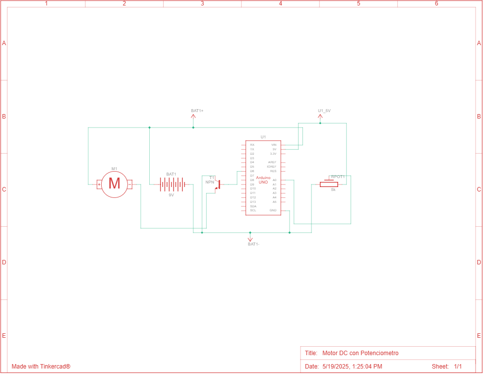
During the session, a circuit was built to control the speed of a DC motor. For this, an Arduino UNO, a mini DC motor, a B1K potentiometer, an NPN-BC547 transistor, DuPont jumpers, and a breadboard were used to assemble the circuit. Below is the circuit diagram and the code.
CIRCUIT DIAGRAM
CODE FOR ARDUINO IDE
const int ledPin = 6;             // Pin connected to the base of the transistor
const int analogPin = A0;         // Pin connected to the potentiometer
int val = 0;                      // Variable to store the potentiometer readingint leerRPM() {
  int rpm = map(analogRead(analogPin), 0, 1023, 0, 2467); // Map the input to RPM range
  return rpm; // Return the RPM value
}
void setup() {
  pinMode(ledPin, OUTPUT);        // Set the transistor control pin as output
  Serial.begin(9600);             // Initialize serial communication
}
void loop() {
  val = analogRead(analogPin);    // Read the potentiometer input
  analogWrite(ledPin, val / 4);   // Scale the value to fit the 0-255 range for PWM
  // Print the RPM value to the Serial Monitor
  Serial.print("RPM = ");
  Serial.print(leerRPM());
  Serial.println(" RPM");
  delay(500); // Small delay to avoid flooding the Serial Monitor
}
It is worth noting that the code uses a function to read the RPMs of the motor. This function required prior calibration, starting by calculating the percentage of the analog signal from the potentiometer.
This value is 183/1023 = 0.17888563049853372434017595307918.
Then, a slow-motion, timed video was recorded to measure the revolutions of the motor at that percentage, yielding:
103 rev / 14 sec × (60 sec / 1 min) = 441.42857142857142857142857142857 RPM
Using a proportional relationship, the maximum RPM is:
441.428571 RPM / 0.178885 = 2467.658079
LEARNINGS & APPLICATIONS
With this project, you will learn more about how a transistor works. Basically, it is the driver that modifies the current received by the motor, allowing its speed to vary. You will also get to visually display the motor’s RPM in real time. In our case, we observed how the motor reached 2467 RPM. To achieve this, we first measured the RPM using video and implemented the result in the original code. Additionally, this has potential applications in more complex future control projects. Finally, designing and fabricating components is always a pleasant addition to any project, even if it wasn't required.