
Prusa Core One Buddy 3D Camera Redux
Obliczymy ostateczną cenę na podstawie wybranego pliku. Sprawdzisz ją i zaakceptujesz przed płatnością.
Zapisane na tym urządzeniu.

Update to my original Buddy 3D Camera Redux, now for internal mounting to the Prusa Core One No screws, nuts or magnets!
- Ocena
- 5 / 5
- Polubienia
- 23
- Pobrania
- 73
- Wydruki
- 6
- Wyświetlenia
- 1351
- Oceny
- 6
Aktualizacja u źródła:
Informacje o modelu
- Źródło
- Printables
- Kategoria
- Prusa Parts & Upgrades
- Licencja
- Creative Commons — Attribution — Noncommercial
This is an update to my original Buddy 3D Camera Redux - now specifically made for internal mounting to the Prusa Core One.
The design is simplified and still clicks together with no screws, but is also much more robust.
I chose to drop internal mounting points for Mic, Speaker and battery - as I do not use these features - but you can still keep them connected and just pack them in - no problem.
The mount to the frame is press fit into any four top corners using the features of corner profile using a star shaped locking system.
There are only 6 printed parts and no screws, nuts or magnets.
This star mount release system supports routing the cable down, left and right depending on the placement. The USB-C connector is not fixed to the enclosure but sits inside with the USB-c cable end, kept inside and locked by the grooves. I chose this solution to keep it simple, as the internal mounting creates a safe space for the strain relief.
The antenna is routed towards the top plate and has a plastic protector to keep the antenna strip safe.
Support is not needed, except for the Front Shell where "build plate only" should be enabled. as It will make small supports for the side locking wings that is floating in mid air.
I have included a .3mf with all the set up
Here is a guide:
- Print all 6 parts. Only the Front Shell needs supports. I reccomend setting perimeters to 16 to make parts all perimeters. Do not use PLA as it will soften too much inside the enclosure. PETG should be sufficient but PCCF or similar should also work.
IMPORTANT: For the Rear Shell only - make sure your material will allow for the spring bending action needed for mounting inside the printer. PCCF or similar might be to stiff and brittle.
- Disassemble the Buddy 3D camera. Please see my original Buddy 3D Camera Redux page for a quick guide. If you have my old redux - disassemble all parts. Only the small reset button printed part from the old redux is indentical, nothing else. Take care when removing the antenna sticker, and speaker.
- Disconnect the mic and put it aside (You can optionally keep it)
- Disconnect the speaker and put it aside (You can optionally keep it)
- Disconnect the orange battery and put it aside (You can optionally keep it)

Front view of the disassembled camera, with the re-used parts shown.
Rear view of the disassembled camera, with the re-used parts shown.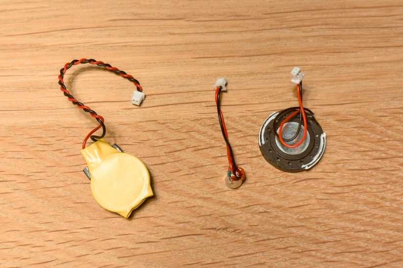
Speaker, Mic and battery are not needed for normal operation - put them aside
- Carefully insert the Antenna PCB sticker into the Antenna Cover printed part. Note the orientation of groove for the cable/solder and the cable/solder of the antenna - both should face upwards. If the Antenna is too sticky - stick it temporarely onto a piece of fabric. Press it gently into the Printed part with your thumbs while holding the printed part. The PCB sticker should disappear totally inside the Plastic. Do not fold the antenna - or ripple it.

The Antenna PCB sticker is inserted into the printed part, orient the sticker so you have the wire/solder pointing up and the printed part oriented so the groove for the wire is also pointing up. Slowly push the sticker inside - holding the printed part with two hands and pushing on the sticker with your thumbs.
The sticker should be fully hidden inside the part.
- Take the Front Shell with the open rear facing up
- Insert the IR emitter ring from the rear. To clear the top part of the print, just angle it a bit. When looking from the front, the small light sensor hole should point straight at the slot in the front


- Insert the Print into the housing from the rear, and orient the SD card slot towards the cutout in the print. Guide the lens into the center hole of the IR emitter ring.
Insert the PCB fully inside the shell, make sure all 4 standoffs are fully seated flush with the top of the PCB.
- Place the Reset button in the front shell. Observe that the button has a flat side and a beveled side - the flat side needs to face up.

- Place the antenna cable in the groove in the top of the front shell

- Take the Rear Shell, and guide the USB-C PCB thru the slid, and loosely place the rear shell on the top of the front shell - DO NOT PRESS DOWN AND CLOSE THE GAP YET!


- Make sure that the antenna cable is sitting in the groove and not is squeezed between the shells.

- Make sure the Reset button is still in place

- Now hold the front and rear shells shells closely together with one hand, and attach the first slider, by sliding in from the top of the shells (where the antenna is located)
Just slide it half way and repeat with the other slider, to fix the shells from moving
- Now press both sliders all the way to the end, make sure the end is flush.

- Repeat with the other slider on the other side.
- Attach a USB-C to USB-C cable to the USB-C PCB.
- Wiggle the USB-C PCB and the connected USB-C cable connector back inside the shell thru Triangle and route the cable in the preferred groove (Down, Left and Right). The default groove would be straight down.
- Inside the printer, route the other end of the cable in the preferred corner (default is front left) from above the extruder plane behind the Z stepper, thru the small corner cutout.
- While pulling the cable downwards move the camera enclosure towards the top corner
- The three legs of the triangle mount will engage the small cutouts in the Core One enclosure. Start with engaging one of the lower legs so it sticks out of the cutout, then wiggle the camera until the other lower leg is sticking out, and lastly snap the top one into place.


- Make sure the antenna is placed against the top on the top acrylic and out of the way of the extruder cables.
- Route the USB-C cable the same way as the front stepper cable, below the extruder platform. If you are lazy just lay it loosely on the side shell on top of the side handle screws and route it out the back.
If you are good: strip it to the stepper cable to make sure it doesn't interfere with the Y-rails
- Remove the rear core one cable protector by unscrewing it from the inside using the two center Torx screws on either side of the back Z axis leadscrew.
- On the back of the printer route the USB-C cable to the USB-C power connector on the back of the machine.
- Place the cable protector back on the printer, making sure the USB-C cable is routed into the cutout on the cable protector.