
Mushroom arduino led lamp
Obliczymy ostateczną cenę na podstawie wybranego pliku. Sprawdzisz ją i zaakceptujesz przed płatnością.
Zapisane na tym urządzeniu.

Mushroom lamp with changable colors, intensity and more using arduino.
- Ocena
- 0 / 5
- Polubienia
- 29
- Pobrania
- 63
- Wydruki
- 0
- Wyświetlenia
- 607
- Oceny
- 0
Aktualizacja u źródła:
Informacje o modelu
- Źródło
- Printables
- Kategoria
- Home Decor
- Licencja
- Creative Commons — Attribution — Noncommercial — Share Alike
Introduction
Honestly i made this because i was quite bored and also i wanted something cool for my bedroom but when i finished it my father convienced me to leave it in living room because he liked it, so thats what happened and when my grandparents came for visit they all really liked it even though they arent into crazy weird-core lsdeeee magic lamps.
What does it do
This beautiful creation has basically three modes.
- Changing colors using two potentiometer ( two values into "square" data rgb + yellow)
- Random color transition, led intensity is changeble by one potentiometer and transion time is controlled by the second
- Random color showing up, potentiometers work the same like in the last mode
Hardware
The components should be easily obtainable, i used the most common ones. I do not recommend buying them on temu btw because you may end up wirh burned house but i dont care really honestly.
| 2 x potentiometer | for example PK1023d  |
| switch on/off | slide switch button (the size must be 4x9mm)  |
| mode switch | push button(12,2x12,2mm) with square top/ touch sensor  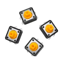 |
| arduino | arduino nano/uno (board that has at least 3 pwm pins), but better are smaller boards because they fit easily 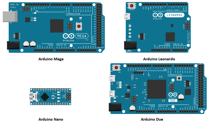 |
| 5 x leds | rgb leds with common cathode  |
| adapter | you may use any dip break-out adapter that will split dc to vcc and gnd (o  r more)  |
Some of the parts are powered by digital pins instead of regular gnd or 5v its safe but it will shorten the lifespan of arduino.
Software
#include <Arduino.h>int state = 4;
int vcc= 2;
int vcc2= 5;
int gnd= 3;
int gnd2= 13;
int b_pin= 9;
int g_pin=10;
int r_pin=11;
int mode=0;
float intensity;
int OldbuttonState;
struct colors {int intblue;
int intred;
int intgreen;
int intyell;};
colors cols;
int sec;
int prim;
int dir1 = random(1,256);
int dir2=random(1,256);
int dir3=random(1,256);
float xVal;
float yVal;
#define pot1 A0
#define pot2 A1
unsigned long Time;
int potTime;
float potInten;
void setup() {
pinMode(b_pin, OUTPUT);
pinMode(g_pin, OUTPUT);
pinMode(r_pin, OUTPUT);
pinMode(vcc, OUTPUT);
pinMode(vcc2, OUTPUT);
pinMode(state, INPUT);
pinMode(gnd, OUTPUT);
pinMode(gnd2, OUTPUT);
Serial.begin(9600);
}
void loop() {
digitalWrite(vcc, HIGH);
digitalWrite(vcc2, HIGH);
digitalWrite(gnd, LOW);
digitalWrite(gnd2, LOW);
int buttonState=digitalRead(state);
if (buttonState==HIGH and buttonState != OldbuttonState){
mode++;
}
OldbuttonState = buttonState;
if(mode==0){
color();
}
else if(mode==1){
change();
}
else if (mode==2){
rndm();
}
else if (mode >=2){
mode=0;
}
xVal = analogRead(pot1);
yVal= analogRead(pot2);
potInten = xVal / 4;
potTime= yVal / 200;
Time= millis();
prim= Time/1000;
}
void color(){
cols.intblue = xVal/ 1023 * (1-(yVal/1023)) * 255;
cols.intred = (1-(xVal/ 1023)) * (1-(yVal/1023)) * 255;
cols.intgreen =xVal/ 1023* yVal/1023 * 255;
cols.intyell = ((1-(xVal/1023))* yVal/1023 * 255)/2;
colorLed();
}
void change(){
if (prim - sec >= potTime){
sec=prim;
if (dir1== cols.intblue){
dir1=random(1,256);
}
if(dir1 >cols.intblue ){
cols.intblue=cols.intblue+1;
}
if(dir1< cols.intblue){
cols.intblue=cols.intblue-1;
}
if (dir2== cols.intgreen){
dir2=random(1,256);
}
if(dir2> cols.intgreen ){
cols.intgreen =cols.intgreen+1;
}
if(dir2< cols.intgreen){
cols.intgreen=cols.intgreen-1;
}
if (dir3== cols.intred){
dir3=random(1,256);
}
if(dir3> cols.intred ){
cols.intred=cols.intred+1;
}
if(dir3< cols.intred){
cols.intred=cols.intred-1;
}
}
cols.intyell=0;
modesLed();
}
void rndm(){
if (prim - sec >= (potTime + 2)){
sec= prim;
cols.intyell =0;
cols.intblue= random(0,256);
cols.intgreen= random(0,256);
cols.intred= random(0,256);
if (cols.intblue == 0 and cols.intgreen==0){
cols.intred= 255;
}
}
modesLed();
}
void modesLed(){
intensity = potInten / 255;
int red = intensity * (cols.intred + cols.intyell);
int green = intensity * (cols.intgreen + cols.intyell);
int blue = intensity * (cols.intblue);
analogWrite(r_pin, red);
analogWrite(g_pin, green);
analogWrite(b_pin, blue);
}
void colorLed(){
analogWrite(r_pin, cols.intred + cols.intyell);
analogWrite(g_pin, cols.intgreen + cols.intyell);
analogWrite(b_pin, cols.intblue);
}
Printing
For mushrooms i used some cheap white pla. For stems i recommend using brim.
Base and potentiometer caps were printed with prusament woodfill. Caps need support.
Print the Topbase_oval/rectangular_parts.stl and Bottombase_oval/rectangular.stl (if you just wanna use different base than the original just print noparts version instead ). Print touch_sensor_holder.stl if you are using sensor, if you are using button print button_cap.stl
Final initicialization ( with arduino)
- Wire leds on very long wires (at least 20cm, for American people™ its probably 1,2 of ben and jerries ice cream box or two glazed donuts) using small bread board or tinned breadboard and then cut it to make it fit into box. Basically connect all r pins, g pins, b pins and cathode pins together. Without wires it should look like this:

2. Solder wires to button,switch,potentiometers or use breadboard.
3. Connect to arduino and upload it, digital gnds and vccs use for potentiometers or button(leds are to consuming). This is how the switch with adapter circuit will look like(- is gnd, + is vcc adapter). Orange wire is vin pin.

4. try to make it fit and honestly good luck.