
Bachmann Hornby 0-4-0 Adapter
Obliczymy ostateczną cenę na podstawie wybranego pliku. Sprawdzisz ją i zaakceptujesz przed płatnością.
Zapisane na tym urządzeniu.
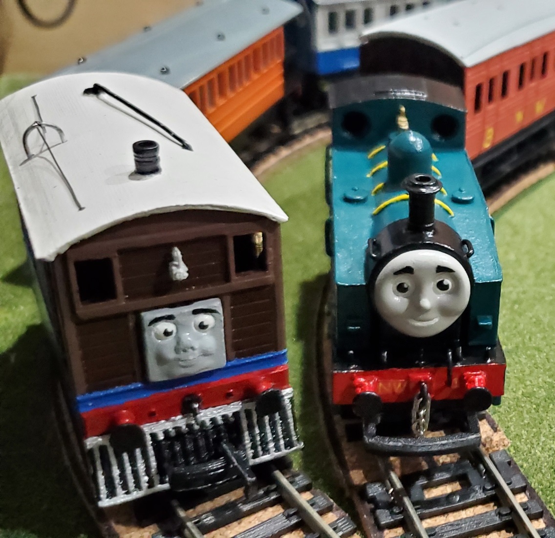
Being in the United States, getting replacement parts for British model locomotives can be challenging, un-…
- Ocena
- 0 / 5
- Polubienia
- 6
- Pobrania
- 76
- Wydruki
- 0
- Wyświetlenia
- 1566
- Oceny
- 0
Aktualizacja u źródła:
Informacje o modelu
- Źródło
- Printables
- Kategoria
- Other Ideas
- Licencja
- Creative Commons — Attribution
Being in the United States, getting replacement parts for British model locomotives can be challenging, un-environmental, or impossible. but I found that the Bachmann Percy chassis shares a similar wheelbase to the 0-4-0's, and the Bachmann Duck wheels are also similar in size to their wheels. so I made up new addons for a Bachmann Percy Chassis using a custom Motor Housing shared with my Castle In The Sky Loco ( https://www.thingiverse.com/thing:5240690 ).
this is designed to fit underneath hopefully any Hornby 0-4-0 shell. as part of this, I've included a back piece, and two front's with and without cylinders. there are also two versions of each piece, one for Percy wheels (15mm Dia) and for Duck wheels (16mm Dia). for parts, you will need the following
Motor (Bach Edward and Emily): https://estore.bachmanntrains.com/index.php?main_page=product_info&cPath=68_93_160&products_id=7240
Percy Chassis: https://estore.bachmanntrains.com/index.php?main_page=product_info&cPath=68_93_99&products_id=810
https://estore.bachmanntrains.com/index.php?main_page=product_info&cPath=68_93_99&products_id=809
https://estore.bachmanntrains.com/index.php?main_page=product_info&cPath=68_93_99&products_id=807
Screw's https://estore.bachmanntrains.com/index.php?main_page=product_info&cPath=68_93_99&products_id=4046
https://estore.bachmanntrains.com/index.php?main_page=product_info&cPath=68_93_94&products_id=4004
Kitbash pickups set https://estore.bachmanntrains.com/index.php?main_page=product_info&cPath=752_717&products_id=11655
note, the gear connecting the motor to the drive gear is not sold on its own on their site. if the provided printed gear is causing problems for you, I can recommend the gear in the following link's assembly. the gear is shared between Bachmann Thomas and Percy. https://estore.bachmanntrains.com/index.php?main_page=product_info&cPath=68_93_99&products_id=806
if you choose to use Ducks wheels (16mm Dia) his wheels were only available as part of Ducks underframe ATM. https://estore.bachmanntrains.com/index.php?main_page=product_info&cPath=68_93_599&products_id=5723
the only thing I couldn't find in Bachmann parts was part of many of the side rods. this should be easy to substitute with paper clips or small metal dowels. just find something that's about 1.2mm. 1mm could work it will just be loose.
Print Settings
Printer Brand:
Prusa
Printer:
I3 MK3S
Rafts:
No
Supports:
Yes
Resolution:
.15mm
Infill:
less then 10%
Filament: Generic PLA is fine
black recommended Post-Printing =============
assembly
when you have printed everything, you should have the following printed
1x chassis back
1x chassis front (w/ or w/o pistons)
1x chassis clip
1x motor housing L&R
1x Optional replacement gear
and a set of the coupling hook+ loop coupling assembly
the motor assembly should go together fairly clearly. either use a small screw or glue the pickups to the sides of the motor housing. you can then solder the wires to the motor. and screw together. after which screw to the chassis. you can adjust the screw to adjust the motor housing. if it isn't losing you may need to enlarge the hole slightly on the chassis.
for the parts of the chassis that will screw to the Percy chassis, you need to cut short segments for the chassis end, there should be holes for those to be glued into, you can then screw it to the corresponding end of the chassis. it should be obvious which end it will screw into. mainly the original front of the Percy chassis that's now the rear. the front part will need the clip to be glued into the holes in it are to help secure it in place and hopefully prevent it from being pulled up from it. then take the rods that help hold the crosshead in line and either press-fit or glue them into the house above and below the larger hole for the rod of the crosshead. once done, screw the assembly to the other end now you are done, grease/oil the joint and gearing and let it run in for 30min's in both directions. then you can either put wight inside where possible or put a Hornby 0-4-0 top on the chassis.
the couplings use a paperclip as the join and screw onto the front and back of the printed ends of the chassis.
also, share what you made and what you used for the tops! I would love to see them.
Category: Hobby