
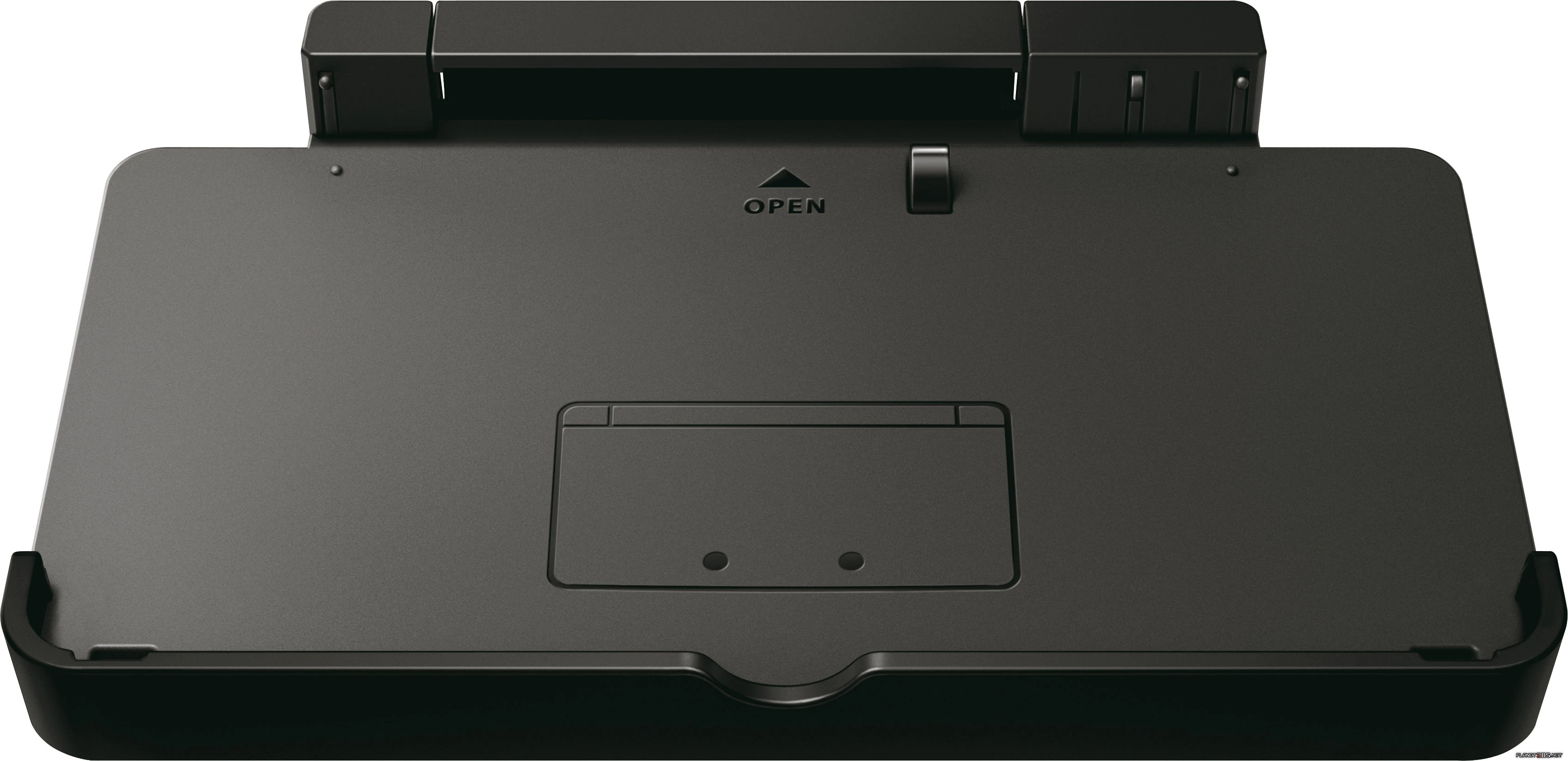
New Nintedo 3DS Charging Cradle (functional)
Obliczymy ostateczną cenę na podstawie wybranego pliku. Sprawdzisz ją i zaakceptujesz przed płatnością.
Zapisane na tym urządzeniu.

This print takes the Original Nintendo 3DS's Charging Cradle (CTR-007) and converts it to work with the New Nintendo 3DS
- Ocena
- 0 / 5
- Polubienia
- 2
- Pobrania
- 4
- Wydruki
- 0
- Wyświetlenia
- 25
- Oceny
- 0
Aktualizacja u źródła:
Informacje o modelu
- Źródło
- Printables
- Kategoria
- Video Games
- Licencja
- Creative Commons — Attribution — Noncommercial
This print allows you to transform an Original Nintendo 3DS Charging Cradle into a dock for the New Nintendo 3DS.
As stated above, this print takes the electronic components from the Original Nintendo 3DS Charding Cradle (model CTR-007, reference image) and converts it into a functional charging dock that ONLY works with the New Nintendo 3DS. It took quite a lot of testing but I am proud to say I've done it :)
Beneath are Assembly Instructions for the Charging Unit, Print Recommendations, and Tech Specs for anyone who wants to make additional add-ons!
Assembly Instructions:
Below is an animated version of the assembly of the Charging Unit. Please in addition refer to the text instructions for important information and guidance.

Obtain and Disassemble the Charging Cradle. Ensure you keep the main board and the golden prongs attached and at minimum 4 screws. The Charging Cradle has the model number CTR-007, and uses specialized tri-point (Y0) screws. Note that not using the proper screwdriver can strip the screws and make disassembly impossible. (image of cradle, example disassembly, example screwdriver)
Place the board inside the body of the Charging Unit by sticking the center hole into the peg on the wall. Make sure that the plug is not sticking out of the assembly, and that it is in the direction of the wall. You may need to tilt the board in order for it to fit.
Position the prongs into the slot. From the perspective of the slots facing you, the positive (red-wired) prong is in the right slot, and the negative (black-wired) prong is in the left slot.
Insert a screw into the circular hole bordering the wall and ensure that the prong is screwed through. Double check that you are not screwing through the square hole where the soldering is attached. Don't screw in the screw too loosely or too tightly, screw it until the prongs begin to compress.
Place the lid on top of the current assembly, ensuring that the cables are not pinched in the process and using the screw holes on the bottom screw in the lid tightly. You may need to cram in the wiring but it should not affect you too much, just ensure that the cables are not being pinched by the lid or could be screwed through. (Tip: If the lid does not seem to close, the connector on the board may be misaligned or there may be a wire being pinched between the lid and the body, reposition the board at a 90° angle and clear all wires from the way and the lid should fit flush.)
You have now completed assembly! Simply insert the Charging Unit into the Cradle and it should add charging functionality to the Charging Cradle!
Important Notice: When inserting the Charging Unit, you may need to push down on the prongs to avoid them getting caught on the walls. Please take caution since if you do not notice this then your prongs will get bent out of shape if crushed!
Print Recommendations:
I personally recommend using your high-quality print profile (if you have one) and turning on supports. Position supports within the slot on the dock, taking care to put it inside the small overhang and also the more larger slot for the prongs, on the Charging Unit's body within the screw holes on the bed, underneath the peg sticking out and the overhangs for the sliding in part, and optionally some on the radius for the lid (if printed upside down, which I highly recommend).
Specs:
The slot used for the dock is a 35mm by 5mm center box, with the little things sticking out being 5/3mm down from the top, and a 5/3mm square (sorry for the weird numbers lol) and in addition there is a tolerance deduction of 0.0625mm in any part contacting the walls (minus the top). If you want the "scale" models I used or an image of the sketches in Fusion then please feel free to reach out :)