
1 / 7
3d printed tripod
Zamów wydruk tego modelu
Obliczymy ostateczną cenę na podstawie wybranego pliku. Sprawdzisz ją i zaakceptujesz przed płatnością.
Zapisane na tym urządzeniu.

Tripod with head for video and photography, 3d printable with Petg and TPU.
- Ocena
- 5 / 5
- Polubienia
- 361
- Pobrania
- 976
- Wydruki
- 2
- Wyświetlenia
- 10 887
- Oceny
- 2
Aktualizacja u źródła:
Informacje o modelu
- Źródło
- Printables
- Kategoria
- Photo & Video
- Licencja
- Creative Commons — Attribution — Noncommercial — Share Alike
SzczegółyPliki (22)Wydruki i komentarze (Wydruki: 2) (Komentarze: 3)Remiksy (1)Kolekcje (474)Powiązane
PRINTABLE TRIPOD
Simple but functional tripod with a maximum extension of about 1,30 meters, design also includes a 3-axis head.
BILL OF MATERIALS
PRINTED PARTS
All parts doesn't require supports, also STLs are already oriented for printing.
N. | PHOTO | NAME | INFILL | PERIMETERS | MATERIAL | Q.TY |
| 1 |  | Body | 40 | 3 | PETG | 1 |
| 2 |  | 12 - 16 joint | 40 | 3 | PETG | 3 |
| 3 |  | 16 - 20 joint | 40 | 3 | PETG | 3 |
| 4 | 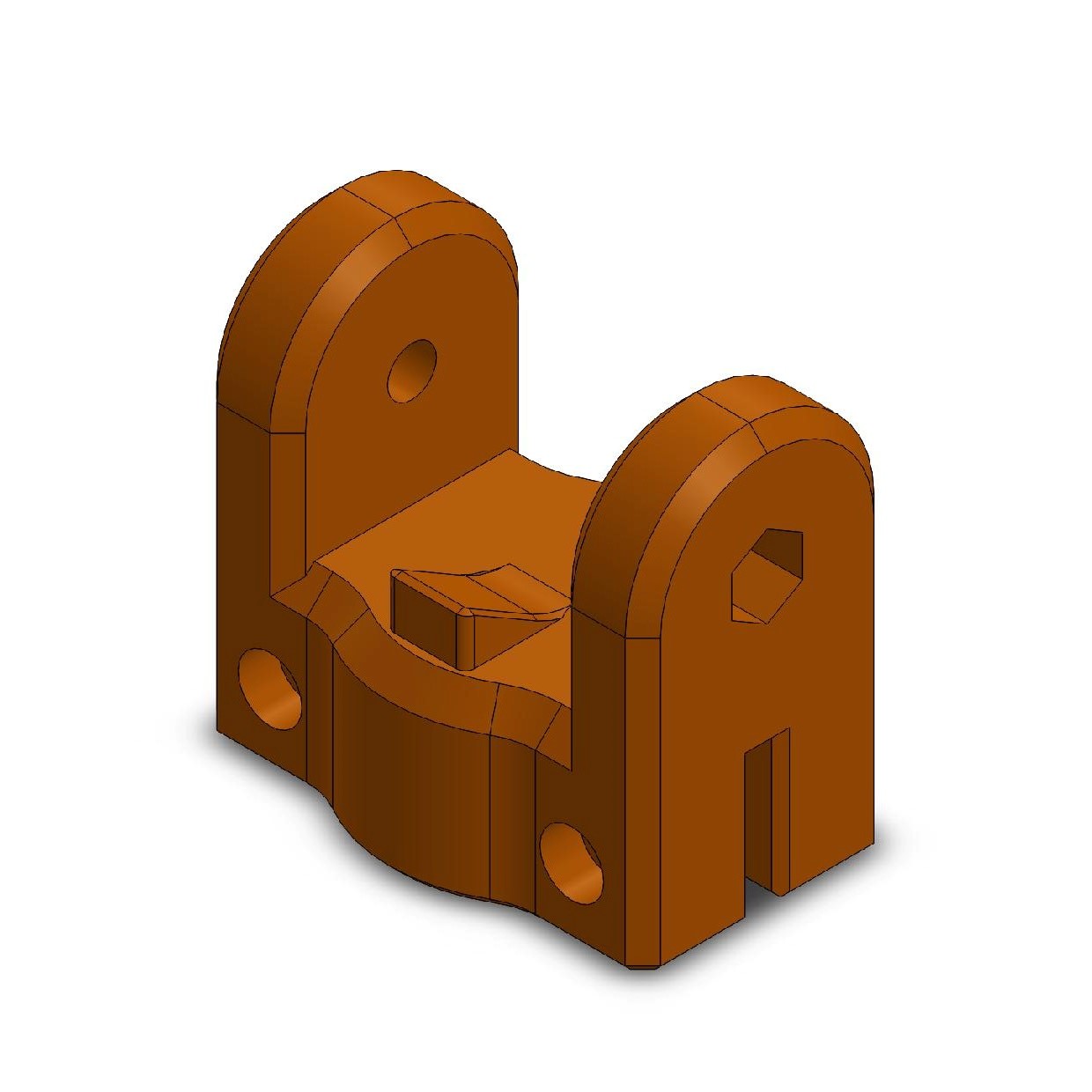 | Leg joint | 40 | 3 | PETG | 3 |
| 5 |  | Foot | 20 | 2 | TPU 95A | 3 |
| 6 |  | Endstop 12 | 40 | 3 | PETG | 3 |
| 7 |  | Endstop 16 | 40 | 3 | PETG | 3 |
| 8 |  | Column cap | 20 | 2 | TPU 95A | 1 |
| 9 |  | TPU cap | 100 | 2 | TPU 95A | 1 |
| 10 |  | Leg knob | 20 | 2 | PETG / PLA | 6 |
| 11 |  | Head knob | 20 | 2 | PETG / PLA | 3 |
| 12 | 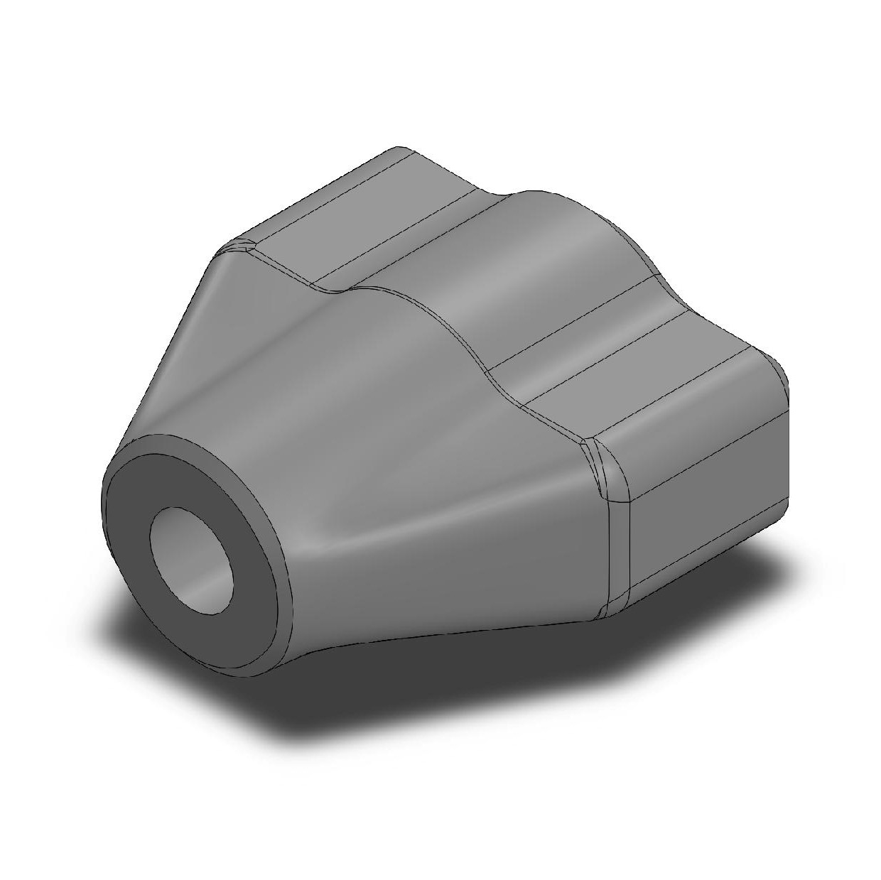 | Column knob | 20 | 2 | PETG / PLA | 1 |
| 13 |  | Knob cap | 20 | 2 | PETG / PLA / TPU | 9 |
| 14 |  | Knob cap small | 20 | 2 | PETG / PLA / TPU | 1 |
| 15 |  | Head joint | 40 | 3 | PETG | 1 |
| 16 |  | Rotating base | 40 | 3 | PETG | 1 |
| 17 |  | Rotating base cap | 40 | 3 | PETG | 1 |
| 18 |  | Tilting cylinder | 40 | 3 | PETG | 1 |
| 19 |  | Tilting head | 40 | 3 | PETG | 1 |
| 20 |  | Camera base cylinder | 40 | 3 | PETG | 1 |
| 21 |  | Camera base | 40 | 3 | PETG | 1 |
| 22 |  | Camera base cap | 40 | 3 | PETG | 1 |
TUBES
N° | NAME | EXT Ø | INT Ø | LENGTH | MATERIAL | Q.TY |
| 23 | 20 - 320 Tube | 20 | 18 | 320 | Anodized aluminum | 4 |
| 24 | 16 - 300 Tube | 16 | 14 | 300 | Anodized aluminum | 3 |
| 25 | 12 - 280 Tube | 12 | 10 | 280 | Anodized aluminum | 3 |
SCREW AND BOLTS
N | PHOTO | NAME | Q.TY |
| 26 |  | M3 x 10 socket head screw | 2 |
| 27 |  | M4 x 16 socket head screw | 6 |
| 28 |  | M4 x 25 socket head screw | 8 |
| 29 |  | M5 x 45 socket head screw | 3 |
| 30 |  | M4 x 25 hex head screw | 1 |
| 31 |  | M4 x 35 hex head screw | 9 |
| 32 |  | M4 x 40 hex drive flat head screw | 3 |
| 33 |  | M3 nut | 2 |
| 34 |  | M4 nut | 10 |
| 35 |  | M4 locknut | 12 |
| 36 |  | M5 locknut | 3 |
| 37 |  | Camera screw* | 1 |
*For the camera screw I use this (https://amzn.eu/d/7YtbWqY) from Amazon (NOT AFFILIATE LINK)
ASSEMBLY
Knobs assembly
A knob

- Insert an M4 x 35 hex head screw (31) inside leg knob (10);
- Push the knob cap (13) inside knob to disguise the screw.
B knob

- Insert an M4 x 35 hex head screw (31) inside head knob (11);
- Push the knob cap (13) inside knob to disguise the screw.
C knob

- Insert an M4 x 25 hex head screw (30) inside column knob (12);
- Push the knob cap small (14) inside knob to disguise the screw.
STEP 1: 12mm leg assembly
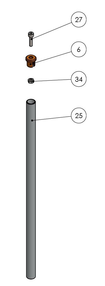
- Insert M4 nut (34) inside endstop 12 (6), then slightly screw M4 x 16 socket head screw(27);
- Push the endstop inside 12 - 280 tube (25). You will have to use a lot of force;
- Now tighten the screw with wrech. With this operation the endstop made more grip with leg beacouse the hexagonal hole is conic and nut push in outside direction.
STEP 2: 12 - 16 joint assembly

- Insert M4 nut (34) and M4 selflock nut (35) inside 12 - 16 joint (2). Pay attention to directions;
- Slightly screw M4 x 16 socket head screw(27) and Leg knob (A).
STEP 3: Joint - leg - feet assembly

- Put the leg inside joint from the top;
- Press leg into the foot (5).
STEP 4: 16mm leg assembly

- Insert M4 nut (34) inside endstop 16 (7), then slightly screw M4 x 16 socket head screw(27);
- Push the endstop inside 16 - 300 tube (24). You will have to use a lot of force;
- Now tighten the screw with wrech. With this operation the endstop made more grip with leg beacouse the hexagonal hole is conic and nut push in outside direction.
STEP 5: 16 - 20 joint assembly

- Insert M4 nut (34) and M4 selflock nut (35) inside 16 - 20 joint (3). Pay attention to directions;
- Slightly screw M4 x 16 socket head screw(27) and Leg knob (A).
STEP 6: Mounting 16mm leg on 12mm leg
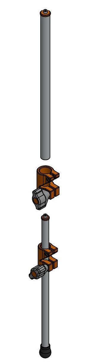
- Insert 16mm leg inside 16 - 20 joint assembly from the top;
- Use the knobs on the joints to block it on the leg;
- Push 16mm leg inside 16mm hole in 12 - 16 joint then thight M4 x 16 screw for blocking the leg inside joint.
STEP 7: Leg joint assembly

- Insert M5 selflock nut (36) inside Leg joint (4);
- Insert M4 selflock nuts (35) inside Leg joint (4) and also insert two M4 x 25 screws (28) but don't tighten.
STEP 8: Complete leg
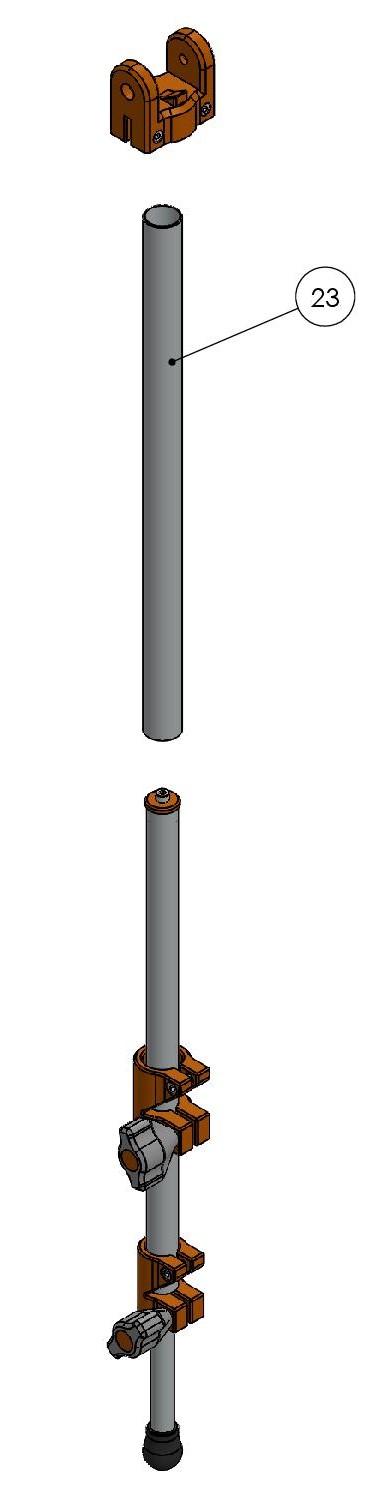
- Insert 20 - 320 tube (23) inside 16 - 20 joint from the top
- Thighten the M4 x 16 screw;
- Insert Leg joint on the top of the leg, then thight M4 x 25 screws.
Repete steps 1 to 8 for the other 2 legs
STEP 9: Center body assembly
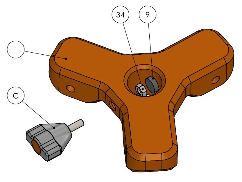
- Insert the M4 nut (34) inside Body (1), for this operation you may need a screw to pull the nut;
- Insert TPU cap (9) on the back of the nut;
- Insert Knob (C) but not tight.
STEP 10: Column assembly
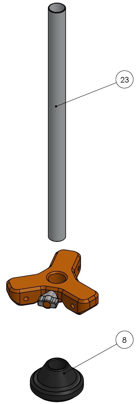
- Insert 20 - 320 tube (23) inside the Body;
- Push Column cap on the bottom of tube.
STEP 11: Assembly legs and base

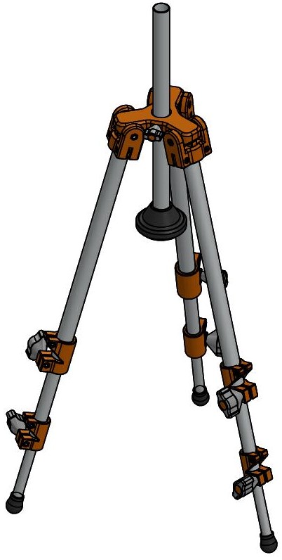
- Join legs and base with M5 x 45 socket head screw (29), thigh the screw enough to make leg stable;
- Leg joint component need to be orientated with the ramp and the head of the screw outside.
STEP 12: Prepare rotating base
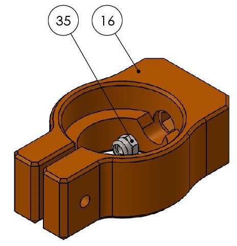
- Push the M4 selflock nut (35) inside Rotating base (16).
STEP 13: Head base assembly
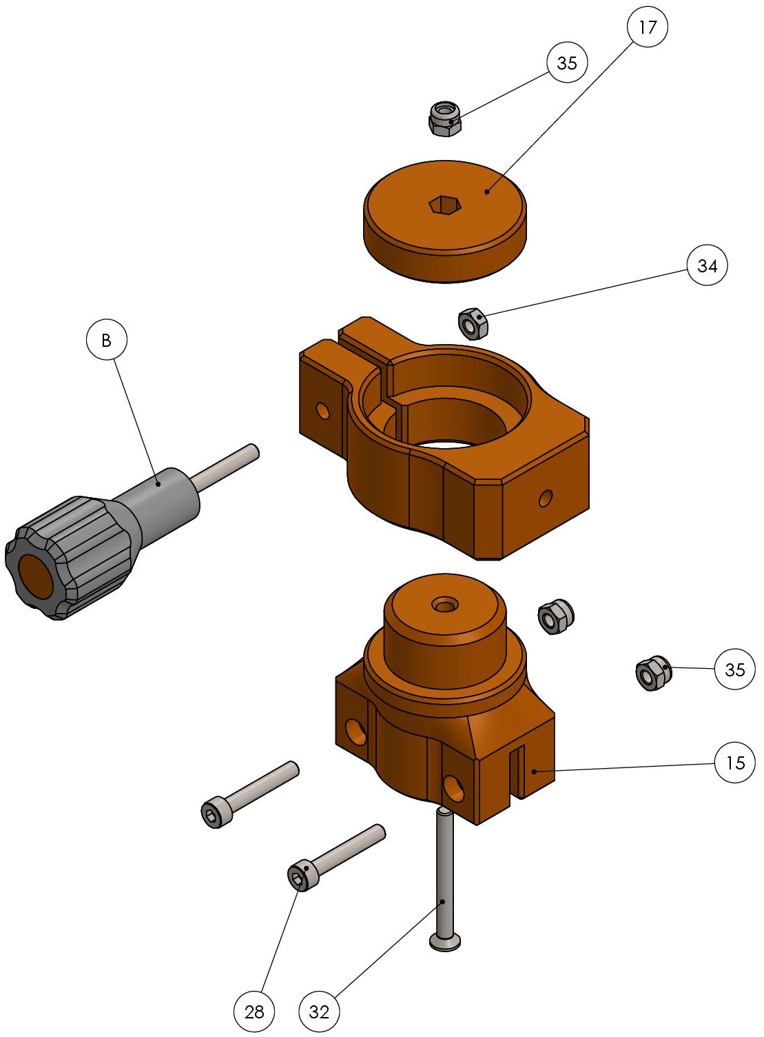
- Push the M4 selflock nuts (35) inside Head joint (15);
- Insert two M4 x 25 socket head screws (28) but don't tight
- Push the M4 selflock nut (35) inside Rotating base cap (17) and an M4 nut (34) inside Rotating base;
- Insert Rotating base on Head joint;
- Insert Rotating base cap in Rotating base and screw it with M4 x 40 hex drive flat head screw (32), make sure that you tightly enough the screw;
- Screw the Head knob (B);
- Make sure everything runs smoothly and the rotating base cap doesn't rotate.
STEP 14: Tilting axis assembly
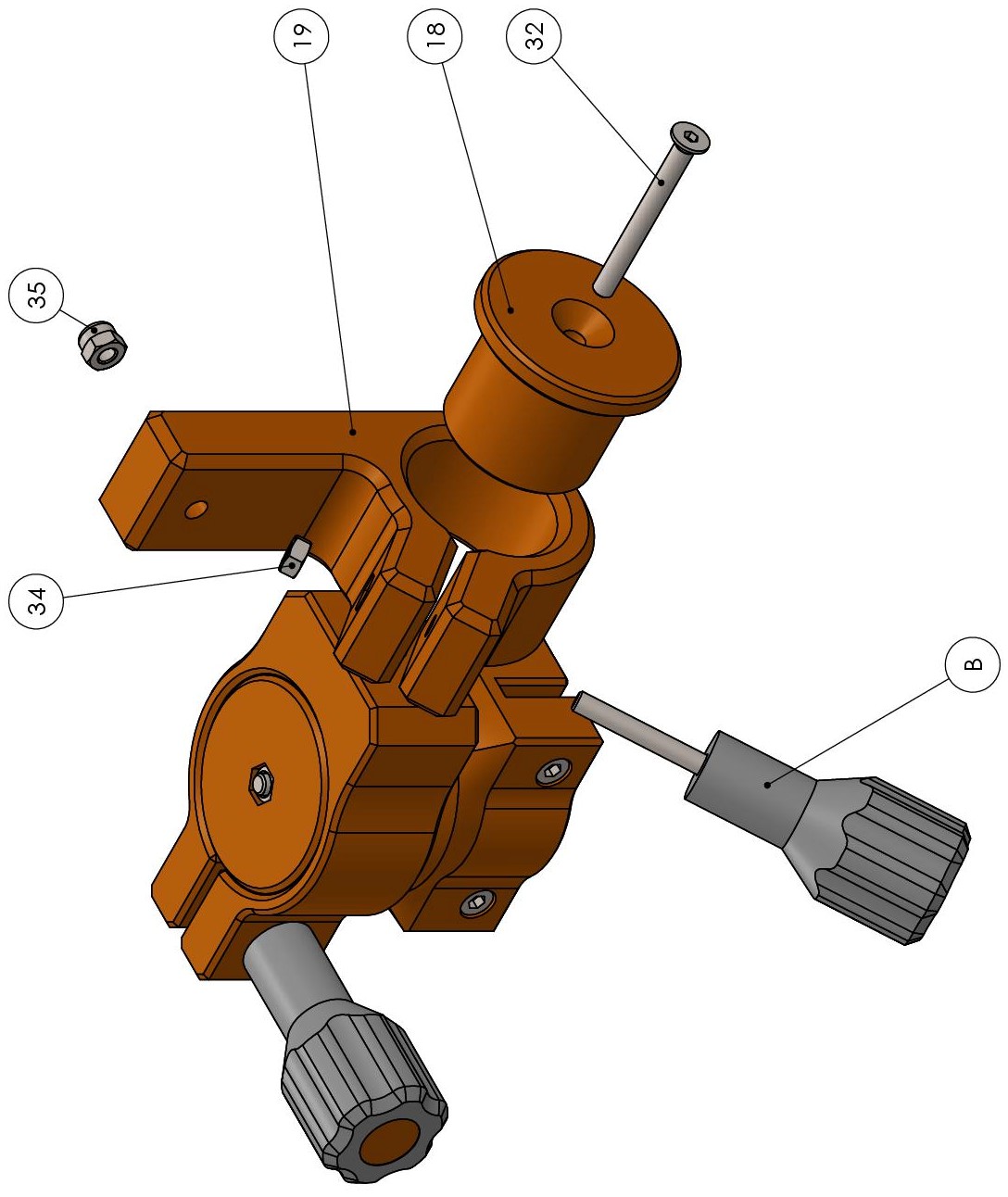
- Push M4 selflock nut (35) inside Tilting head (19);
- Push M4 nut (34) inside Tilting head;
- Mount Tilting cylinder (18)inside Tilting head, after that mount tilting axis on Rotating base with M4 x 40 hex drive flat head screw (32), make sure that you tightly enough the screw;
- Screw the Head knob (B);
- Make sure everything runs smoothly and the Tilting cylinder doesn't rotate.
STEP 15: Camera base assembly

- Insert M4 nut (34) and M3 nuts (33) inside Camera base (21);
- Insert Camera screw inside Camera dase from the back of cut and after fush the screw towards the front;
- Insert Camera base cap (22) and fix it with two M3 x 10 socket head screws (26).
STEP 16: Complete the head

- Mount Camera base cylinder (20) inside Camera base and insert M4 x 40 hex drive flat head screw (32), make sure that you tightly enough the screw;
- Screw the Head knob (B);
- Make sure everything runs smoothly and the Tilting cylinder doesn't rotate.
STEP 17: Mount head on tripod
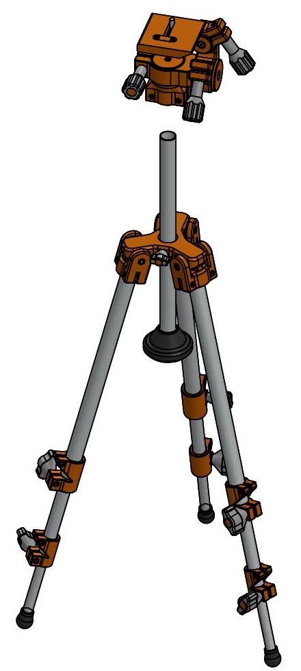
- Insert head on column and thight M4 x 25 socket head screws of the head.