
1 / 7
3d printed tripod
Order a print of this model
We calculate the final price from your selected file. You review and accept it before payment.
Saved on this device.

Tripod with head for video and photography, 3d printable with Petg and TPU.
- Rating
- 5 / 5
- Likes
- 361
- Downloads
- 976
- Makes
- 2
- Views
- 10,887
- Reviews
- 2
Updated at source:
Model information
- Source
- Printables
- Category
- Photo & Video
- License
- Creative Commons — Attribution — Noncommercial — Share Alike
PRINTABLE TRIPOD
Simple but functional tripod with a maximum extension of about 1,30 meters, design also includes a 3-axis head.
BILL OF MATERIALS
PRINTED PARTS
All parts doesn't require supports, also STLs are already oriented for printing.
N. | PHOTO | NAME | INFILL | PERIMETERS | MATERIAL | Q.TY |
| 1 |  | Body | 40 | 3 | PETG | 1 |
| 2 |  | 12 - 16 joint | 40 | 3 | PETG | 3 |
| 3 |  | 16 - 20 joint | 40 | 3 | PETG | 3 |
| 4 | 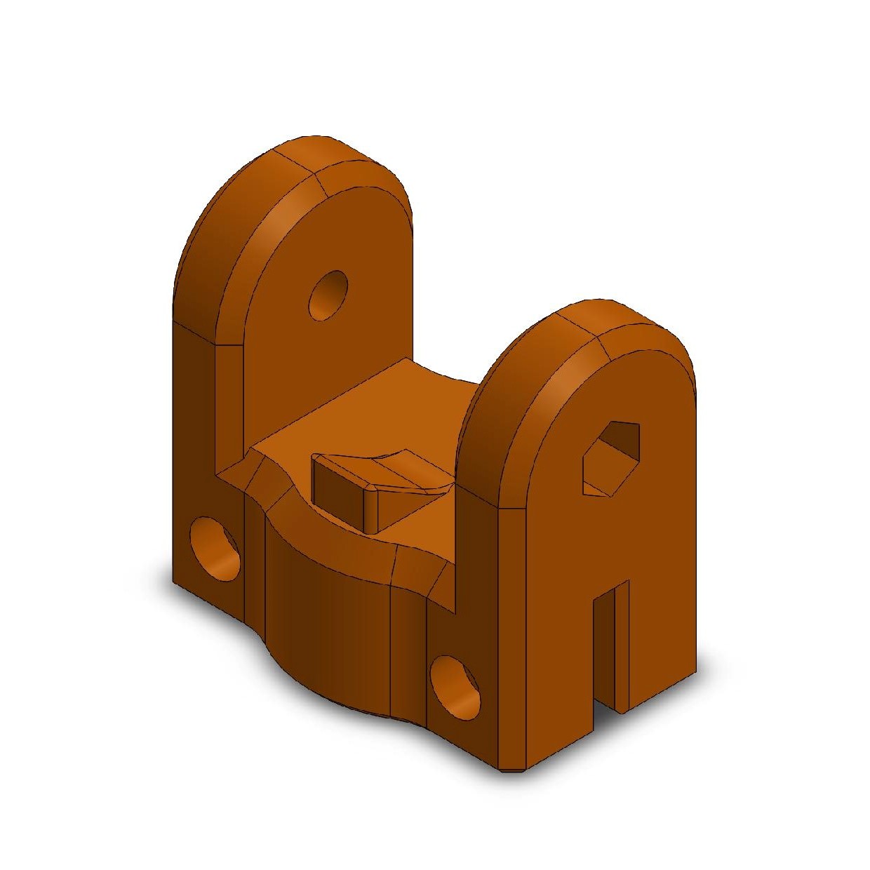 | Leg joint | 40 | 3 | PETG | 3 |
| 5 |  | Foot | 20 | 2 | TPU 95A | 3 |
| 6 |  | Endstop 12 | 40 | 3 | PETG | 3 |
| 7 |  | Endstop 16 | 40 | 3 | PETG | 3 |
| 8 |  | Column cap | 20 | 2 | TPU 95A | 1 |
| 9 |  | TPU cap | 100 | 2 | TPU 95A | 1 |
| 10 |  | Leg knob | 20 | 2 | PETG / PLA | 6 |
| 11 |  | Head knob | 20 | 2 | PETG / PLA | 3 |
| 12 | 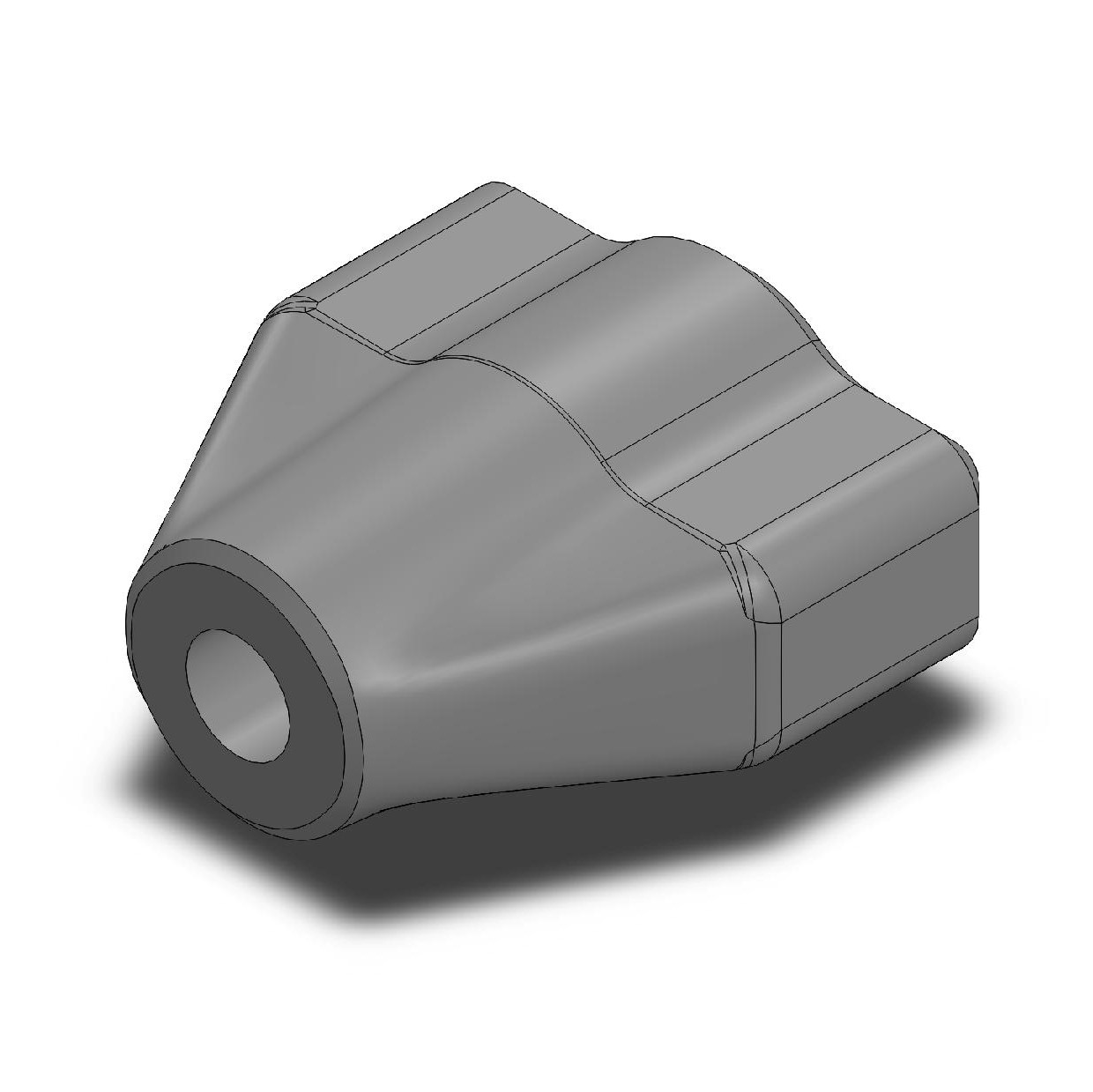 | Column knob | 20 | 2 | PETG / PLA | 1 |
| 13 |  | Knob cap | 20 | 2 | PETG / PLA / TPU | 9 |
| 14 |  | Knob cap small | 20 | 2 | PETG / PLA / TPU | 1 |
| 15 |  | Head joint | 40 | 3 | PETG | 1 |
| 16 |  | Rotating base | 40 | 3 | PETG | 1 |
| 17 |  | Rotating base cap | 40 | 3 | PETG | 1 |
| 18 |  | Tilting cylinder | 40 | 3 | PETG | 1 |
| 19 |  | Tilting head | 40 | 3 | PETG | 1 |
| 20 |  | Camera base cylinder | 40 | 3 | PETG | 1 |
| 21 |  | Camera base | 40 | 3 | PETG | 1 |
| 22 |  | Camera base cap | 40 | 3 | PETG | 1 |
TUBES
N° | NAME | EXT Ø | INT Ø | LENGTH | MATERIAL | Q.TY |
| 23 | 20 - 320 Tube | 20 | 18 | 320 | Anodized aluminum | 4 |
| 24 | 16 - 300 Tube | 16 | 14 | 300 | Anodized aluminum | 3 |
| 25 | 12 - 280 Tube | 12 | 10 | 280 | Anodized aluminum | 3 |
SCREW AND BOLTS
N | PHOTO | NAME | Q.TY |
| 26 |  | M3 x 10 socket head screw | 2 |
| 27 |  | M4 x 16 socket head screw | 6 |
| 28 |  | M4 x 25 socket head screw | 8 |
| 29 |  | M5 x 45 socket head screw | 3 |
| 30 |  | M4 x 25 hex head screw | 1 |
| 31 |  | M4 x 35 hex head screw | 9 |
| 32 |  | M4 x 40 hex drive flat head screw | 3 |
| 33 |  | M3 nut | 2 |
| 34 |  | M4 nut | 10 |
| 35 |  | M4 locknut | 12 |
| 36 |  | M5 locknut | 3 |
| 37 |  | Camera screw* | 1 |
*For the camera screw I use this (https://amzn.eu/d/7YtbWqY) from Amazon (NOT AFFILIATE LINK)
ASSEMBLY
Knobs assembly
A knob

- Insert an M4 x 35 hex head screw (31) inside leg knob (10);
- Push the knob cap (13) inside knob to disguise the screw.
B knob

- Insert an M4 x 35 hex head screw (31) inside head knob (11);
- Push the knob cap (13) inside knob to disguise the screw.
C knob

- Insert an M4 x 25 hex head screw (30) inside column knob (12);
- Push the knob cap small (14) inside knob to disguise the screw.
STEP 1: 12mm leg assembly
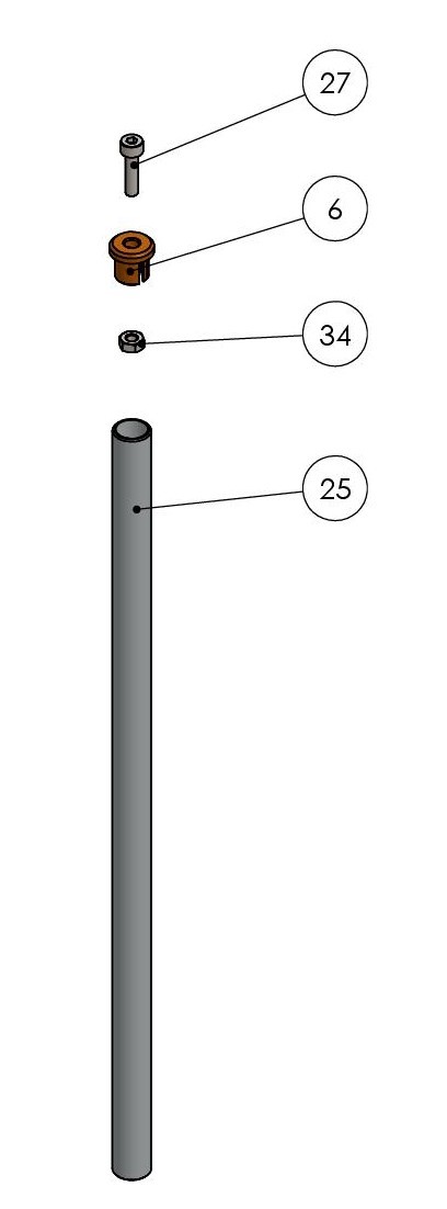
- Insert M4 nut (34) inside endstop 12 (6), then slightly screw M4 x 16 socket head screw(27);
- Push the endstop inside 12 - 280 tube (25). You will have to use a lot of force;
- Now tighten the screw with wrech. With this operation the endstop made more grip with leg beacouse the hexagonal hole is conic and nut push in outside direction.
STEP 2: 12 - 16 joint assembly

- Insert M4 nut (34) and M4 selflock nut (35) inside 12 - 16 joint (2). Pay attention to directions;
- Slightly screw M4 x 16 socket head screw(27) and Leg knob (A).
STEP 3: Joint - leg - feet assembly

- Put the leg inside joint from the top;
- Press leg into the foot (5).
STEP 4: 16mm leg assembly

- Insert M4 nut (34) inside endstop 16 (7), then slightly screw M4 x 16 socket head screw(27);
- Push the endstop inside 16 - 300 tube (24). You will have to use a lot of force;
- Now tighten the screw with wrech. With this operation the endstop made more grip with leg beacouse the hexagonal hole is conic and nut push in outside direction.
STEP 5: 16 - 20 joint assembly

- Insert M4 nut (34) and M4 selflock nut (35) inside 16 - 20 joint (3). Pay attention to directions;
- Slightly screw M4 x 16 socket head screw(27) and Leg knob (A).
STEP 6: Mounting 16mm leg on 12mm leg
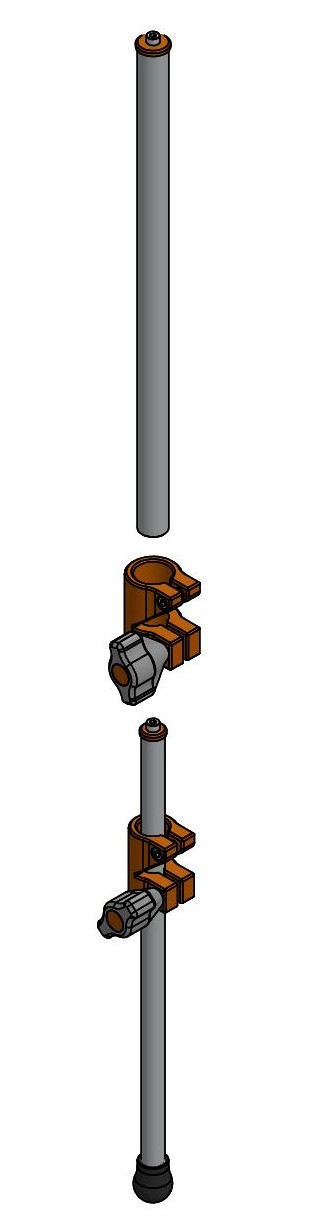
- Insert 16mm leg inside 16 - 20 joint assembly from the top;
- Use the knobs on the joints to block it on the leg;
- Push 16mm leg inside 16mm hole in 12 - 16 joint then thight M4 x 16 screw for blocking the leg inside joint.
STEP 7: Leg joint assembly

- Insert M5 selflock nut (36) inside Leg joint (4);
- Insert M4 selflock nuts (35) inside Leg joint (4) and also insert two M4 x 25 screws (28) but don't tighten.
STEP 8: Complete leg
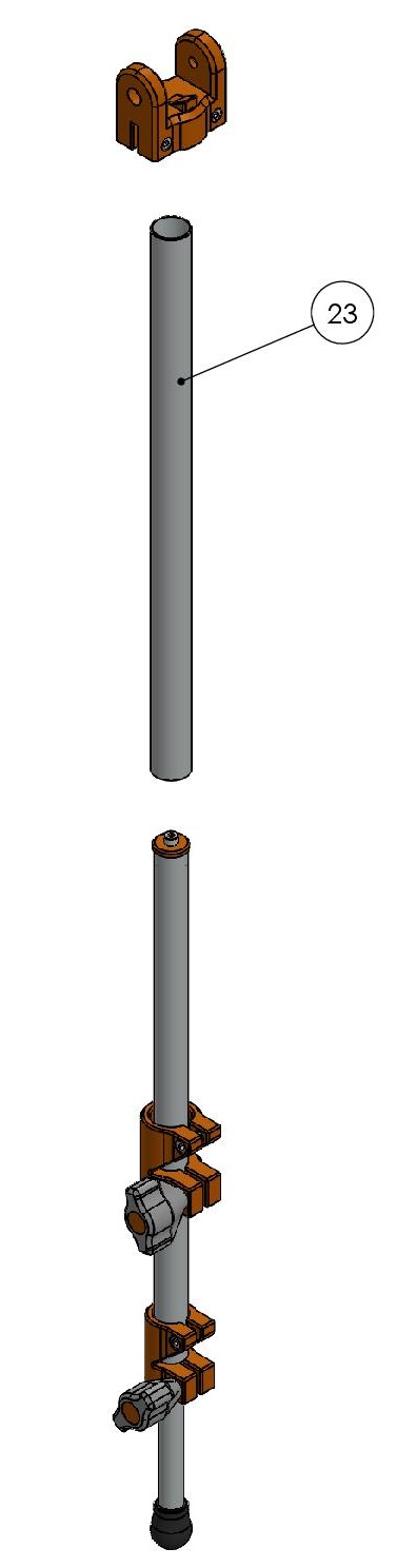
- Insert 20 - 320 tube (23) inside 16 - 20 joint from the top
- Thighten the M4 x 16 screw;
- Insert Leg joint on the top of the leg, then thight M4 x 25 screws.
Repete steps 1 to 8 for the other 2 legs
STEP 9: Center body assembly
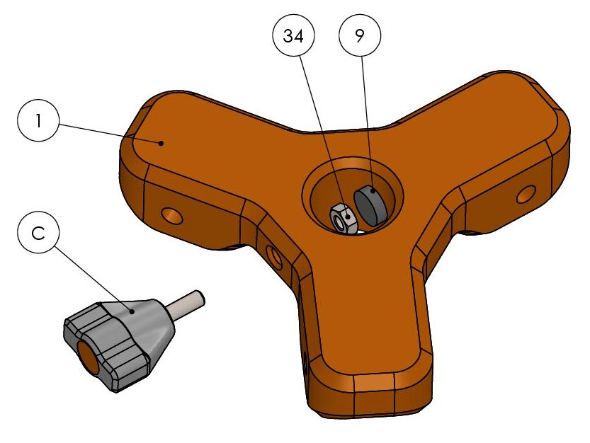
- Insert the M4 nut (34) inside Body (1), for this operation you may need a screw to pull the nut;
- Insert TPU cap (9) on the back of the nut;
- Insert Knob (C) but not tight.
STEP 10: Column assembly
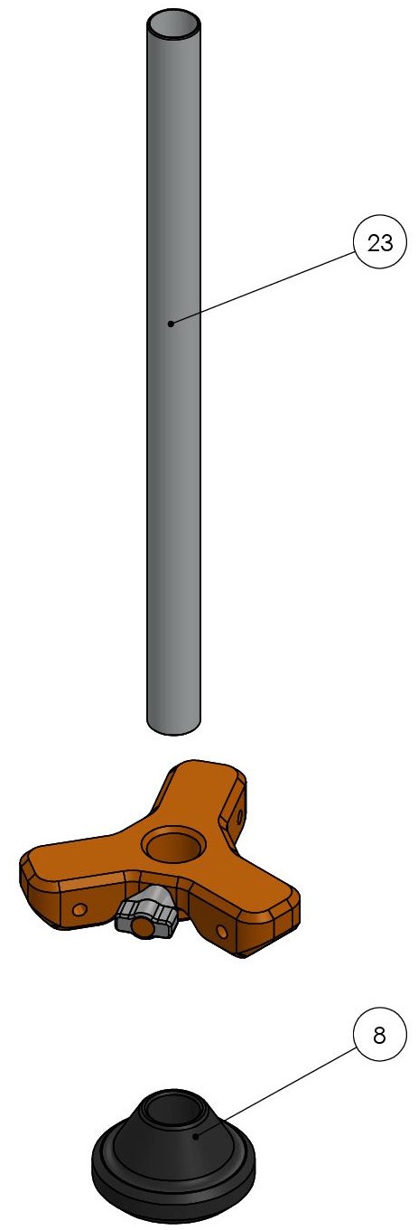
- Insert 20 - 320 tube (23) inside the Body;
- Push Column cap on the bottom of tube.
STEP 11: Assembly legs and base

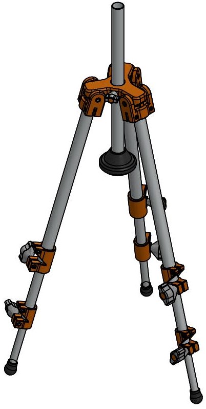
- Join legs and base with M5 x 45 socket head screw (29), thigh the screw enough to make leg stable;
- Leg joint component need to be orientated with the ramp and the head of the screw outside.
STEP 12: Prepare rotating base
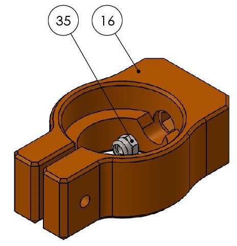
- Push the M4 selflock nut (35) inside Rotating base (16).
STEP 13: Head base assembly
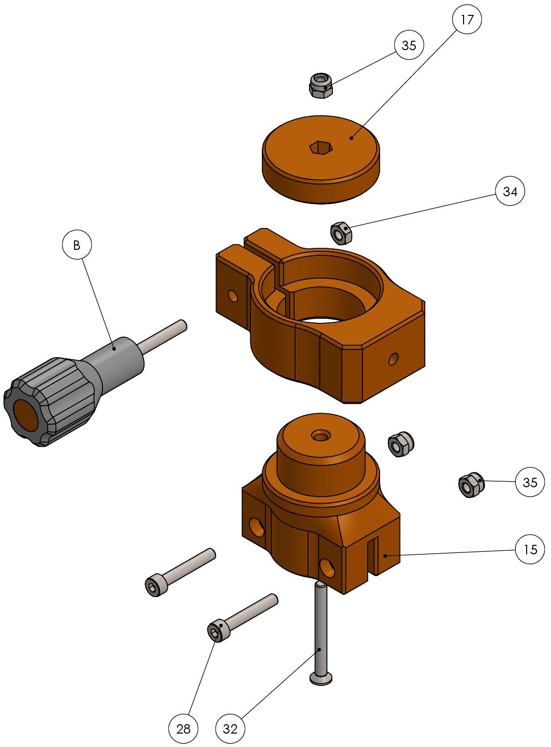
- Push the M4 selflock nuts (35) inside Head joint (15);
- Insert two M4 x 25 socket head screws (28) but don't tight
- Push the M4 selflock nut (35) inside Rotating base cap (17) and an M4 nut (34) inside Rotating base;
- Insert Rotating base on Head joint;
- Insert Rotating base cap in Rotating base and screw it with M4 x 40 hex drive flat head screw (32), make sure that you tightly enough the screw;
- Screw the Head knob (B);
- Make sure everything runs smoothly and the rotating base cap doesn't rotate.
STEP 14: Tilting axis assembly
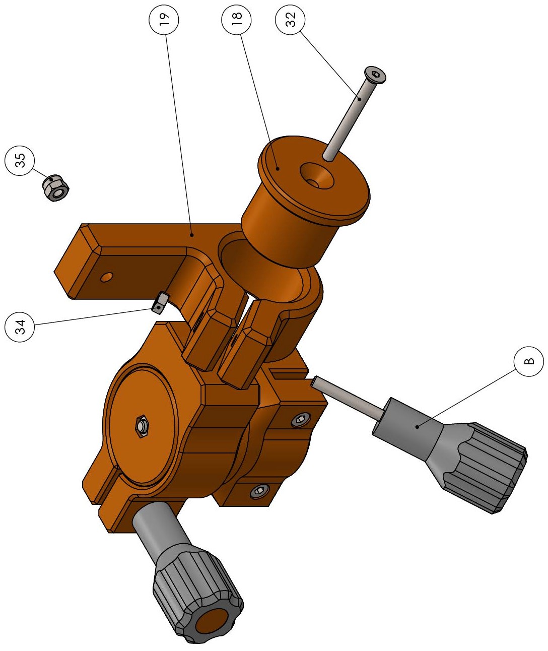
- Push M4 selflock nut (35) inside Tilting head (19);
- Push M4 nut (34) inside Tilting head;
- Mount Tilting cylinder (18)inside Tilting head, after that mount tilting axis on Rotating base with M4 x 40 hex drive flat head screw (32), make sure that you tightly enough the screw;
- Screw the Head knob (B);
- Make sure everything runs smoothly and the Tilting cylinder doesn't rotate.
STEP 15: Camera base assembly

- Insert M4 nut (34) and M3 nuts (33) inside Camera base (21);
- Insert Camera screw inside Camera dase from the back of cut and after fush the screw towards the front;
- Insert Camera base cap (22) and fix it with two M3 x 10 socket head screws (26).
STEP 16: Complete the head

- Mount Camera base cylinder (20) inside Camera base and insert M4 x 40 hex drive flat head screw (32), make sure that you tightly enough the screw;
- Screw the Head knob (B);
- Make sure everything runs smoothly and the Tilting cylinder doesn't rotate.
STEP 17: Mount head on tripod
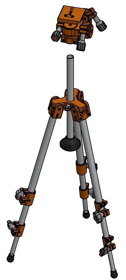
- Insert head on column and thight M4 x 25 socket head screws of the head.