
HAL 9000 Apple TV remote holder
Obliczymy ostateczną cenę na podstawie wybranego pliku. Sprawdzisz ją i zaakceptujesz przed płatnością.
Zapisane na tym urządzeniu.
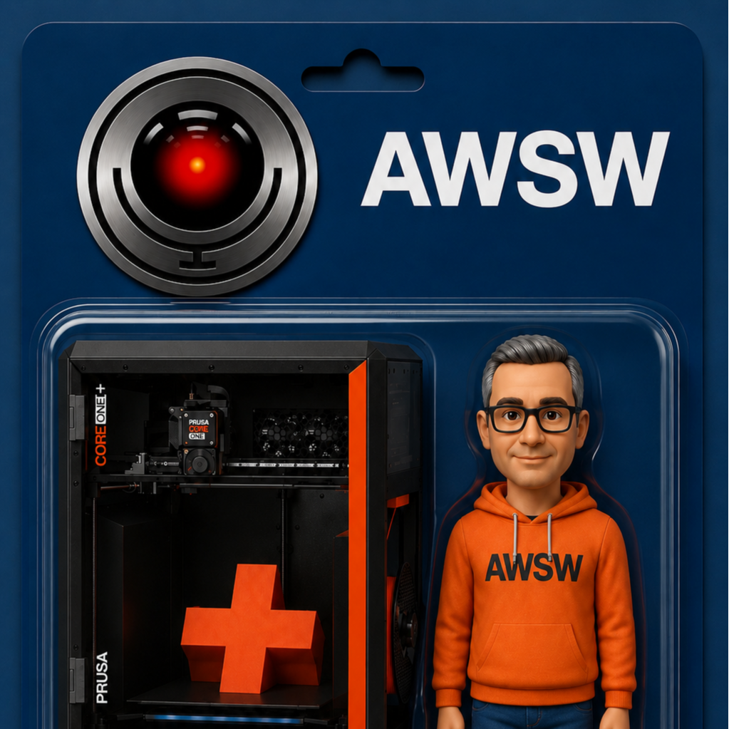
HAL 9000 Apple TV remote holder
- Ocena
- 5 / 5
- Polubienia
- 24
- Pobrania
- 36
- Wydruki
- 2
- Wyświetlenia
- 879
- Oceny
- 1
Aktualizacja u źródła:
Informacje o modelu
- Źródło
- Printables
- Kategoria
- Electronics
- Licencja
- Creative Commons — Attribution — Noncommercial
HAL 9000 Apple TV remote holder.
Who does not remember these legendary sentences?
Dave Bowman: Open the pod bay doors, HAL.
HAL: I'm sorry, Dave. I'm afraid I can't do that.
If you do not, watch this movie: “2001 - A space odyssey“ from 1968 ⚠
So why combine HAL with an Apple device like the Apple TV remote you will ask yourself now…
I am glad you ask... =)
Because Apple did this already 23 years before:
Functions:
- Apple TV remote holder with integrated circuit that simulates the legendary HAL 9000 “breathing” lens light. Most times it was a static red light, but i thought why not make it “breathe” some times…
- Every time you put the remote back into the holder or take it out of it the red light will be activated and will ”breathe” a few times. After that the light will turn off to save power and the circuit waits for the next movement of the remote.
- Also when you move the case it can activate him again too. The strange about this is that I did not tell him to do so by adding this into the code. Oh, what have I done ???!!!??? =)
- The holder contains the complete electronic which is powered by a LiPo battery.
- With the on/off switch you can switch LiPo battery off if you don’t want to use the device.
Video (of a first draft print):
Parts:
- 1x ESP32 Lolin32
- 1x 1100mAh LiPo battery with JST plug (bigger sized ones possible)
- 1x LED chip WS2812B - 1 LED
- 1x optic fisheye lens
- 1x Super glue to glue the Grill part to the base
- 2x M3x8 screws
- 2x M3 nuts
- 2x Soldering cable shoes M3
- Some 0,25mm² wires in different colours
- Optional: 1x Push button Ø12mm (not needed in the current solution)
- 1x On/Off-Switch
Wiring intructions:
| ESP32: | LED chip: | Contact: | Color: |
| 5V | 5V | red | |
| GND | GND | black | |
| 32 | DIN | green | |
| 33 | Pin1 | white | |
| GND | Pin2 | black |
- In addition the switch is put into the +3.7V line (red wire) of the LiPo battery to switch the device on or off to save power.
- The 2 M3 screws are screwed trough the 2 holes in the remote holder
- On the inside the 2 M3 cable shoes are fixed in place with the M3 nuts. The metal case of the remote will close the contact to activate HALs eye…
- The LED chip needs to be put into the LED holder before soldering both wire ends at the LED and the ESP32.
- NOTE: The push button was planed to use, but is not needed in the current solution.
Printing instructions:
- 0.1 detail, 0.2 speed profile or 0.3 draft profile:
- 0.1: LensScrew, LED Holder
- 0.2: CamRing, Sign, BlueSign
- 0.3: Base, Lid, Grill
- Textured sheet used
- Supports needed for the "Base" and "CamRing" part only from the print bed
- The “Base” part should be printed with a 5mm brim to avoid warping
- You will need the following PLA filament colors:
- CamRing, Grill = silver
- LED Holder, Base, Lid, LenseScrew = black
- Sign = Black and white in a color change
- BlueSign = Blue and white in a color change
- Post printing: Depending on the result of the printed LensScrew and LED Holder screw, you might need to screw them several times on the thread to be able to screw both parts on the back of the lens more easily when it sits in the case.
Code:
The needed code can be found in my GitHub repository
Happy printing and stay safe. He's watching… ;-)