
Print in place spring loaded 18650 Battery cell holder / charger TP4056
Obliczymy ostateczną cenę na podstawie wybranego pliku. Sprawdzisz ją i zaakceptujesz przed płatnością.
Zapisane na tym urządzeniu.

here you can find a print in place spring loaded 18650 Battery cell holder that has also a dedicated place for the TP405
- Ocena
- 5 / 5
- Polubienia
- 58
- Pobrania
- 448
- Wydruki
- 4
- Wyświetlenia
- 4555
- Oceny
- 2
Aktualizacja u źródła:
Informacje o modelu
- Źródło
- Printables
- Kategoria
- Electronics
- Licencja
- Creative Commons — Attribution — Share Alike
This is work in progress
next update will be adding an NTC for more safety.
Edited 19-12-2022 : added a little how to and some Data, Features & Technical Specs
After multiple prints and test I finally came with a design that I'm satisfied and I'm sharing it with all the makers
here you can find a print in place spring loaded 18650 Battery cell holder that has also a dedicated place for the TP4056 Charging Module with Battery Protection 18650 BMS 5V Micro USB 1A 186 50 Lithium Battery Charging Board
If you want to charge the battery faster you can do it or by changing the resistance or by staking them if you are interest in this topic just ask ;)
The final version its also have a place to “hide/guide” the cable for a nicer look I hate messy cable management see
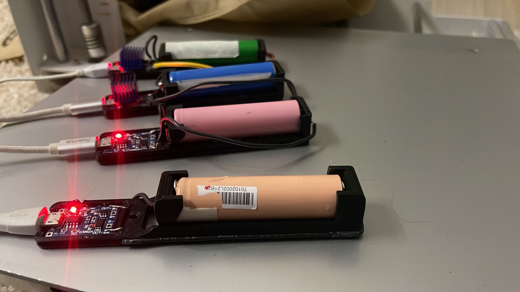

As a request here are some Data regarding this project
As you can see I'm using microUSB to power up the TP4056 module but you can add from 4.5 to 5.5 V to the 5V in + and - near the microUSB port
now you need to solder wires from B+ to the battery plus and from B- to the battery -

Using TP4056 module is very simple for providing input power to the circuit you can use a 5V 2A charger or you can also connect it with any USB outlet. Alternatively you can also connect a 5V 2A supply with the input terminals of the module.
After connecting the supply connect the 3.7V lithium ion cell you want to charge with the battery connections points shown in the image above. The li ion cell should be connected in right polarity or the cell or charger may damage.
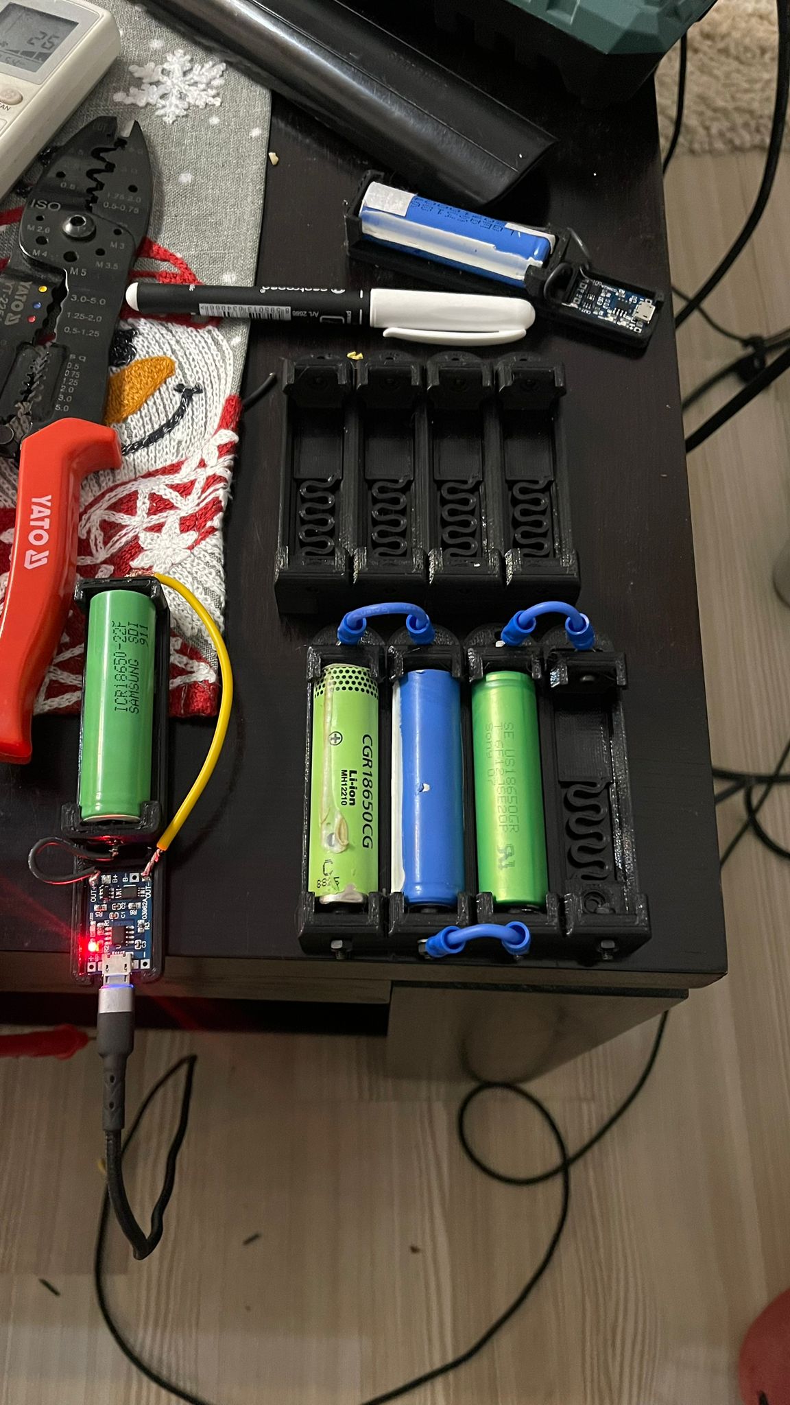
I have made some holes if you want to use M3 screws as terminals for the battery's + and - or you can just run the cable trough the holes from the 3d printed part.
Here you can se in the first photo no screws just running the fire thru the holes and in the second photo you can see the M3x10 and M3 washer.

I want to integrate a rechargeable battery so you don’t have to rely on an external power source. In principle, this might seem trivial, but it’s not. Lithium-polymer and Lithium-Ion batteries (LiIon or LiPo ) are dangerous if they are incorrectly charged, overcharged, overheated or stored incorrectly they can explode. Luckily to make things easier for us and allow us to use a Li-Ion battery in our projects we have several modules that can do some of the work for us. One of these modules is the TP4056.
The main element of the module is the TP4056 chip itself. This chip is a programmable linear current and constant voltage charger for single cell Li-Ion batteries. The module also integrates two LED indicators of the state of charge and two additional chips in charge of the protection of the battery. Although there are versions of the module that do not have these chips, in this case we will use a version that does have these elements like the one described in the image.
The module performs the charging process. First it ensures a constant current until the Li-Ion battery reaches 4.2V. Then, it gradually reduces the charging intensity until the battery is fully charged and ends the charging cycle when the charging current drops to one tenth of the programmed value. It supports input voltages up to 5.5V so it can be used directly connected to a USB port or a mobile charger up to 1.2A Preferably over rule of thumb 2A
| R3 [kΩ] | Charging intensity [mA] |
| 10 | 130 |
| 5 | 250 |
| 4 | 300 |
| 3 | 400 |
| 2 | 580 |
| 1.66 | 690 |
| 1.5 | 780 |
| 1.33 | 900 |
| 1.2 | 1000 |
But if you want more current keep reading we will discus later more
By default it is programmed to charge batteries with an intensity of up to 1Ah although it is possible to reduce this value by replacing resistance R3 with one of a higher value. If you use batteries with a capacity close to 2000 mAh or higher you can leave the resistance used by default, otherwise it is necessary to modify it.
Typically Li-Ion batteries have a maximum charge and discharge current value of 0.5C, i.e. we can apply a charge current less than half its capacity. Using higher currents can reduce battery life or even destroy it. Therefore, depending on the maximum intensity of intensity that we can use in our battery it will be necessary to modify the resistance R3 by one with the value that adjusts to the intensity given in the adjacent table.
In addition, the TP4056 also guarantees the safety of the battery. The DW01A chip is designed to protect from damage and degradation of Li-Ion batteries due to overcharges, over-discharges or current peaks. On the other hand the FS8205A is a chip with a double MOSFET. It is responsible for cutting the power supply to the battery when the charge is complete and prevent its discharge if its voltage drops below 2.5V. A lower value can shorten its life and even render it unusable. It was better if the cutting was made before dropping to 3V.
For this project you will need a cable suitable for the current that you want to use don't go lower than Cable AWG 26 (0.13 mm) I have used AWG 24 0.25mm
I have noticed that the module it gets hot some times up to 60 Celsius so don't use PLA I hade printed mine in PETG and the work just fine.
And also to dissipate the heat I put over the module a heat sink from a step driver that I had Laing around.
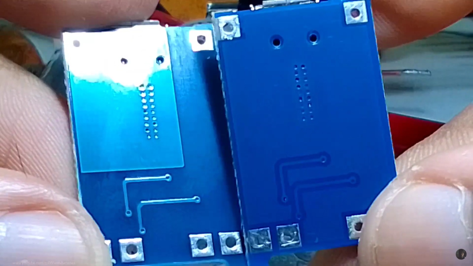
Be careful wen buying the tp module to chose one with protection and also ask for search one with 2layer pcb because they dissipate the heat better because they have like a heatsink
see the copper layer larger helps with heat dissipation (right side in the photo bellow) is also have thicker pcb and better quality components
TP4056 Module Features & Technical Specs:
- Over Current Protection
- Output charging current can be controlled or adjusted from a single resistor
- General Micro USB Female Connector
- Battery Charging Indication LED
- Battery full Charged Indication LED
- Battery auto cutoff from the charging circuit when fully charged
- Soft Start Charging
- It can charge any size of 3.7V Li-ion cell
- Low cost and reliable Li-ion battery charger
- Battery temperature measurement inside (Disconnect charging when temperature of the battery goes high than normal)
- Can connected to any USB port with a USB cable
TP4056 Charging Module Explained / Description:
TP4056 module is a very efficient 3.7V single li ion cell or lithium ion cell charging module. It can not only charge 18650 cell but a wide variety of different sized and kinds of 3.7V li ion batteries. The heart of the module is a TP4056 IC that is an advanced lithium battery charging IC. The IC is built and internally programed to provide efficient charging to a li ion cell which increases the cell back up and life.
The IC also has a temperature input pin from which we can connect a temperature sensor NTC type. The temperature sensor must be attached with the body of the battery to detect the temperature of the battery while charging. The IC is also programed to disconnect the charging when the battery temperature goes above from a limit set inside the IC’s program. The module is also having two indicators LEDs also marked in the module pinout & details above. One LED indicates the battery charging in progress and when the battery become full charged it automatically gets deactivated and the another LED will become activated to indicate that the battery is fully charged.
The max output current of the module is 1A but it can be adjusted with a resistor which we will discuss later in the article.
Output Current Controlling Resistor:
The output charging current of the module can be controlled by a single resistor shown in the above module image. For getting a desired current you have to change this resistor according to your charging current requirements. Here is the list in which you will find which value of resistor will provide how much maximum output current to the battery.
Now lets talk about the serious stuff :D because we all leave in the microwave generation and we want fast charge you can charge your batteries faster using 2 methods.
But first establish something faster charge it means more current more Amps means that you need at least AWG 25 1-3 for more than 4A you will need AWG 21.
AND PLESE if you will use the module for more current use ABS
- First method its to stack more tp4056 modules one over the other. Connect all the 4 corner holes and be careful to be all in the same orientation. See photo bellow

Please do this on your own risk! and if so make sure you have a heat sing and an active cooling system a fan that is cooling the tp4056 module.
- And the second method its to change the R3 resistance
900 OHMs = 1.4A
800 OHMs = 1.7 A
700 OHMs = 2 A
600 OHMs = 2.2 A
if you go lower than 600 Ohms the current will not increase more than 2.2A it may do a peak of 2.4
As you can see from the photos I even use a heatsink on the stock module!
I hope that now everything you need to know for this project is covered, and if anything is unclear, please don't hesitate to ask.
I would appreciate it if you would also post your experience and what you did using this information
kind regards Nadir
the design was inspired using the holder made by K014