
Lenovo 300 FHD Webcam Mount for 3D Printers with 2020 Extrusions
Obliczymy ostateczną cenę na podstawie wybranego pliku. Sprawdzisz ją i zaakceptujesz przed płatnością.
Zapisane na tym urządzeniu.
Allows the Lenovo 300 FHD webcam to be mounted in a 3D printer that uses 2020 extrusions, such as a Voron.
- Ocena
- 0 / 5
- Polubienia
- 6
- Pobrania
- 63
- Wydruki
- 0
- Wyświetlenia
- 1122
- Oceny
- 0
Aktualizacja u źródła:
Informacje o modelu
- Źródło
- Printables
- Kategoria
- Other Printer Parts & Upgrades
- Licencja
- GNU General Public License v3.0
I designed this mount to allow the Lenovo 300 FHD webcam to be used to monitor a 3D printer.
This 1080p USB webcam can be found for as little as US$20 and offers a respectable 95° field of view.
The mount will work with any 3D printer based on 2020 aluminium extrusions, such as a Voron printer.
This design draws in large part on PsychoShaft's C92X mount for its basic design, but with several changes and modifications.
BOM
- 1 x Lenovo 300 FHD webcam
- 2 x M3x35mm (or longer) Socket Head Cap Screw (SHCS)
- 2 x M3 nuts
- 2 x M3x8mm SHCS / Button Head Cap Screw (BHCS)
- 2 x M3x5x4mm heatset inserts (i.e. ‘Voron spec heatsets’)
- 1 x M3x6mm SHCS
- 1 x M3 roll-in T-nut
Print settings
This has been designed to be printed with typical ‘Voron settings’:
- 0.2 layer height
- 4 perimeters/walls
- 5 top/bottom layers
- 40% infill
All parts were designed with ABS in mind. If you want to print the mount with another material, you may need to consider shrinkage/scaling if you have part fitment issues.
Disassembling the Lenovo 300 FHD webcam
Before you begin - disassembly of the Lenovo 300 FHD is irreversible. If you want to reuse this US$20 webcam to become a famous Twitch streamer later on, you might want to hold off on this modification.
Step 1:
The factory monitor mount is held onto the body of the webcam by a hidden small screw. To access this screw there are two options: (1) drill a hole or (2) pry apart the mount.
Option 1: Drill method
Carefully drill a small hole in the underside of the monitor mount directly above the centre of the ‘ball’ that the webcam pivots on like so:

Go slowly - this is plastic after all - and be careful not to damage the screw you are trying to access as you will reuse it later.
Option 2: Pry method
Get a small flat-head screwdriver or similar. Raise up the edge of the silicone material on the underside of the monitor mount and then completely remove the silicone.
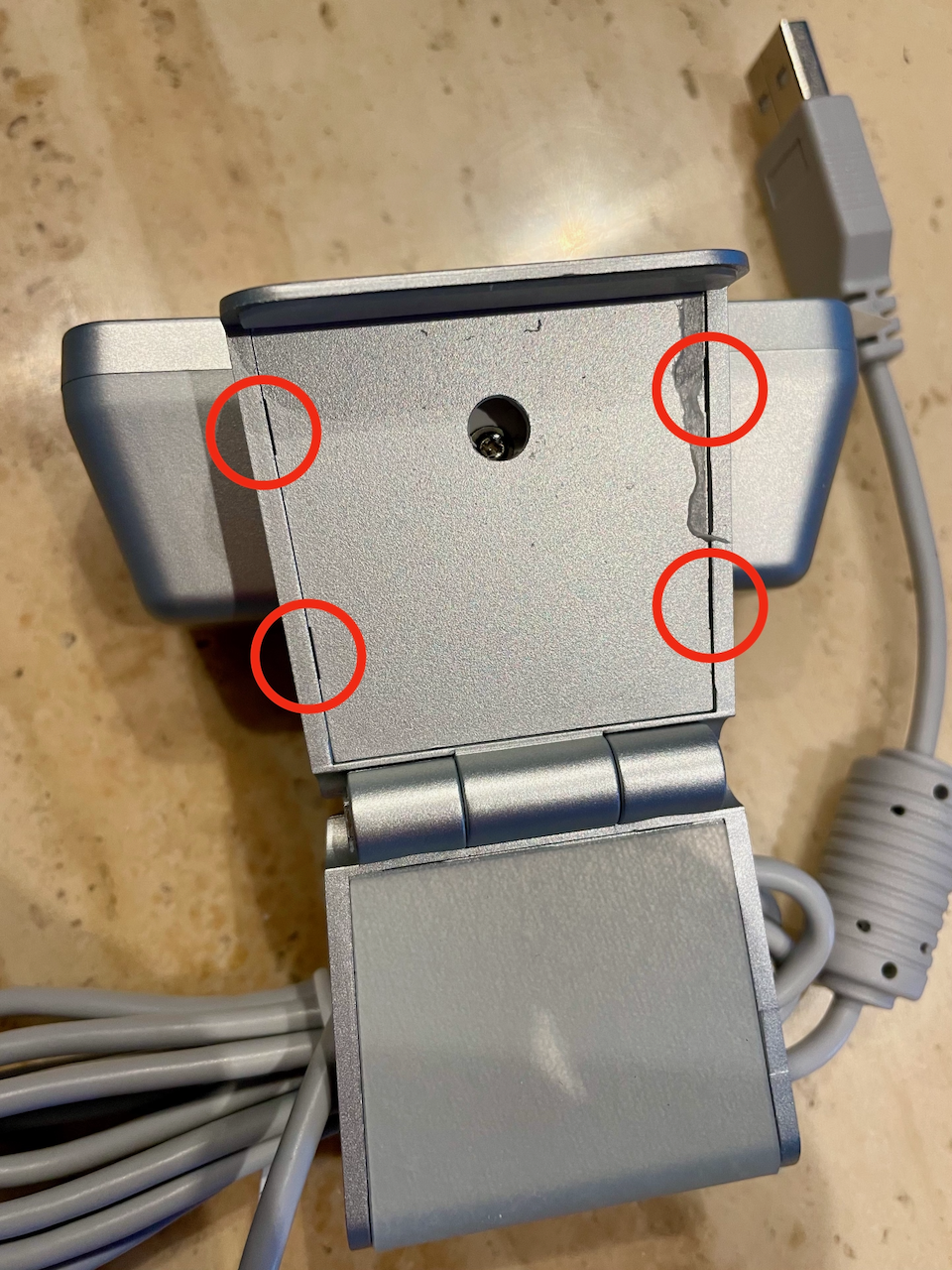
Use the screwdriver to pry up the base using the four small slots as indicated below:
Step 2:
Once you have access to the screw holding the monitor mount to the webcam, carefully unscrew it - you do not want to damage the screw or the threads in the plastic.
Set aside the screw and the white rubbery hemisphere object that it screws into. The hemisphere will pop out of the hole it sits in with some gentle persuasion.

Assembling and installing the new mount
With all parts printed, assembly is very straight forward.
Step 1:
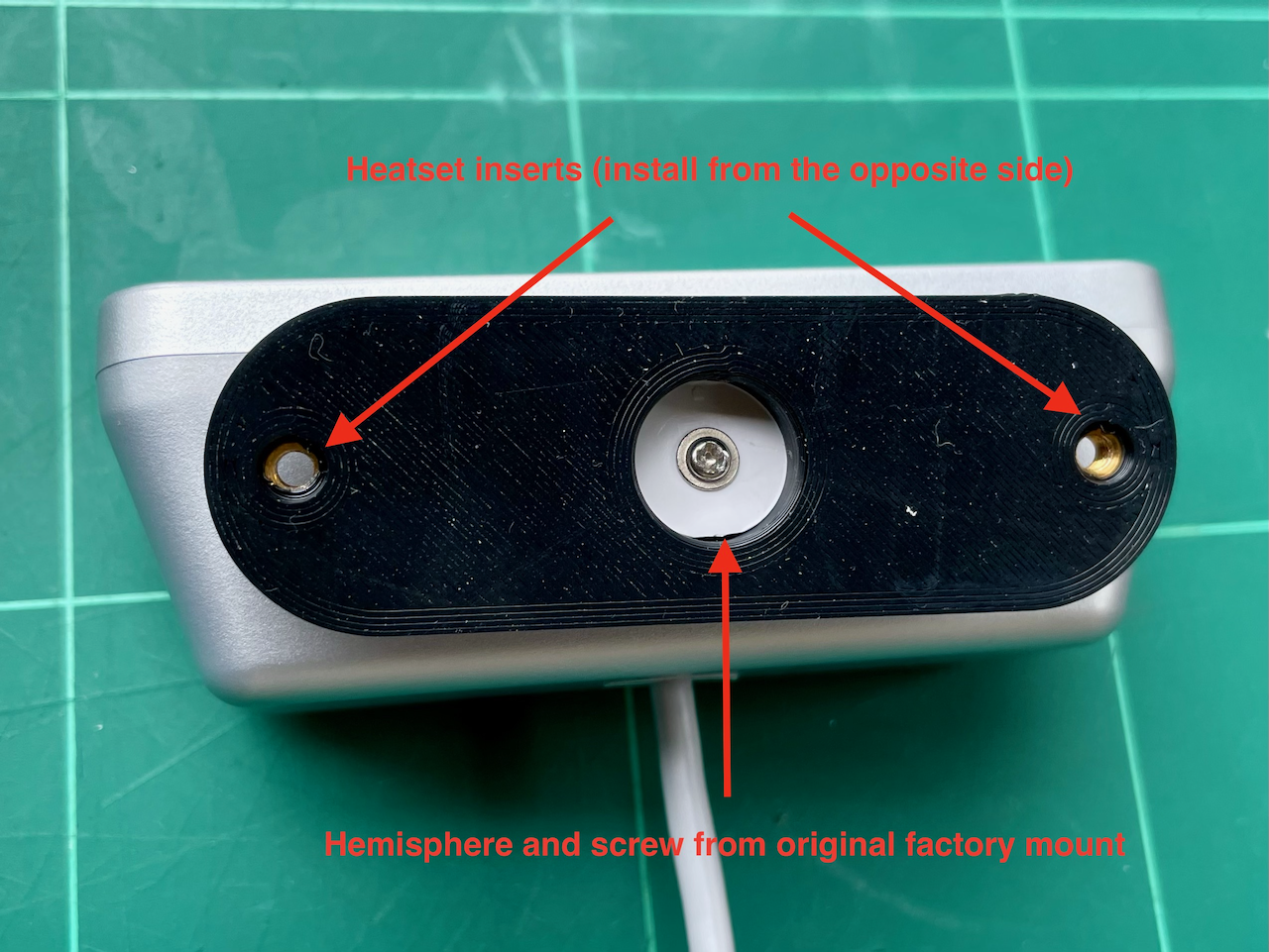
Install the heatset inserts into the printed part that attaches to the webcam. These should be installed from the side facing towards the webcam; there is a chamfer on the hole to assist with installation.
Step 2:
Press the rubbery hemisphere salvaged from the original factory monitor mount into the new printed piece. The fit should be snug and the hemisphere may need some encouragement to press into place.
Step 3:
Fit the printed part containing the hemisphere onto the spline of the webcam. Note that the spline and hemisphere are keyed (i.e. not perfectly round), so ensure you have them oriented correctly before pressing them together.
Once pressed together, reinstall the screw salvaged from the mount. This should be torqued reasonably tightly (but do not go crazy; it is a small self tapping screw going into plastic).
Step 4:
Install the roll-in T-nut into the aluminium extrusion and then screw the relevant printed part into the T-nut using the M3x6mm SHCS.
Step 5:
Assemble the remaining parts of the mount:


Step 6:
Run the USB cable through your printer's frame and adjust the camera position to your desired angle(s). Voila!