
1 / 2
Digital Crazy Hours and Minutes - WiFi Sync Clock
Zamów wydruk tego modelu
Obliczymy ostateczną cenę na podstawie wybranego pliku. Sprawdzisz ją i zaakceptujesz przed płatnością.
Zapisane na tym urządzeniu.

Introducing a mechanical digital clock with numbers strangely arranged.
- Ocena
- 5 / 5
- Polubienia
- 52
- Pobrania
- 174
- Wydruki
- 2
- Wyświetlenia
- 1385
- Oceny
- 1
Aktualizacja u źródła:
Informacje o modelu
- Źródło
- Printables
- Kategoria
- Other Gadgets
- Licencja
- Creative Commons — Attribution — Noncommercial — Share Alike
SzczegółyPliki (16)Wydruki i komentarze (Wydruki: 2) (Komentarze: 7)Remiksy (1)Kolekcje (62)Powiązane
Introducing a mechanical digital clock with numbers strangely arranged.
Technical highlights
- Usually, intermittent motion mechanism such as Geneva drive is necessary to decrease the number of the motors of mechanical digital clock. Contrary, this clock has a constant mesh (permanently engaged reduction gear) between tens and ones places of minute numbers. The ratio of the reduction gear is coprime (7 : 10) and 70 numbers can be shown by one motor.
- The order of the numbers are not random but optimized to minimize the time to update. Average angle of rotation of the central rotor is less than 360 degrees.
- To show the current time correctly when it is powered on, not only the WiFi connection capability but also origin finding mechanism are necessary. This clock has an one-way rotation blocking mechanism. The rotors for minutes are stopped at 00 when it moves backward, but pass through there when rotating forward.
- Herringbone gears are used to hold the rotors without central axes.
Note : This model needs large (30x30cm) 3D printer to make.
Video
Supplies


- two 28BYJ-48 stepper motors and driver board (around 2USD each)
- one M5Stamp-C3 micro controller with WiFi (5.90 - 6 USD)
- cables for pin headers
- M2 tapping screws with various lengths
- short M3 tapping screws (used to attach the stepper motor)
- lubricant (silicone oil or grease)
How to make


- Print parts with supplied posture.
- No supports needed.
- Print 8 copies of "holding-gear-8copies.stl" and "gear-fix-8copies.stl".
- Remove debris and blobs from the printed parts well.
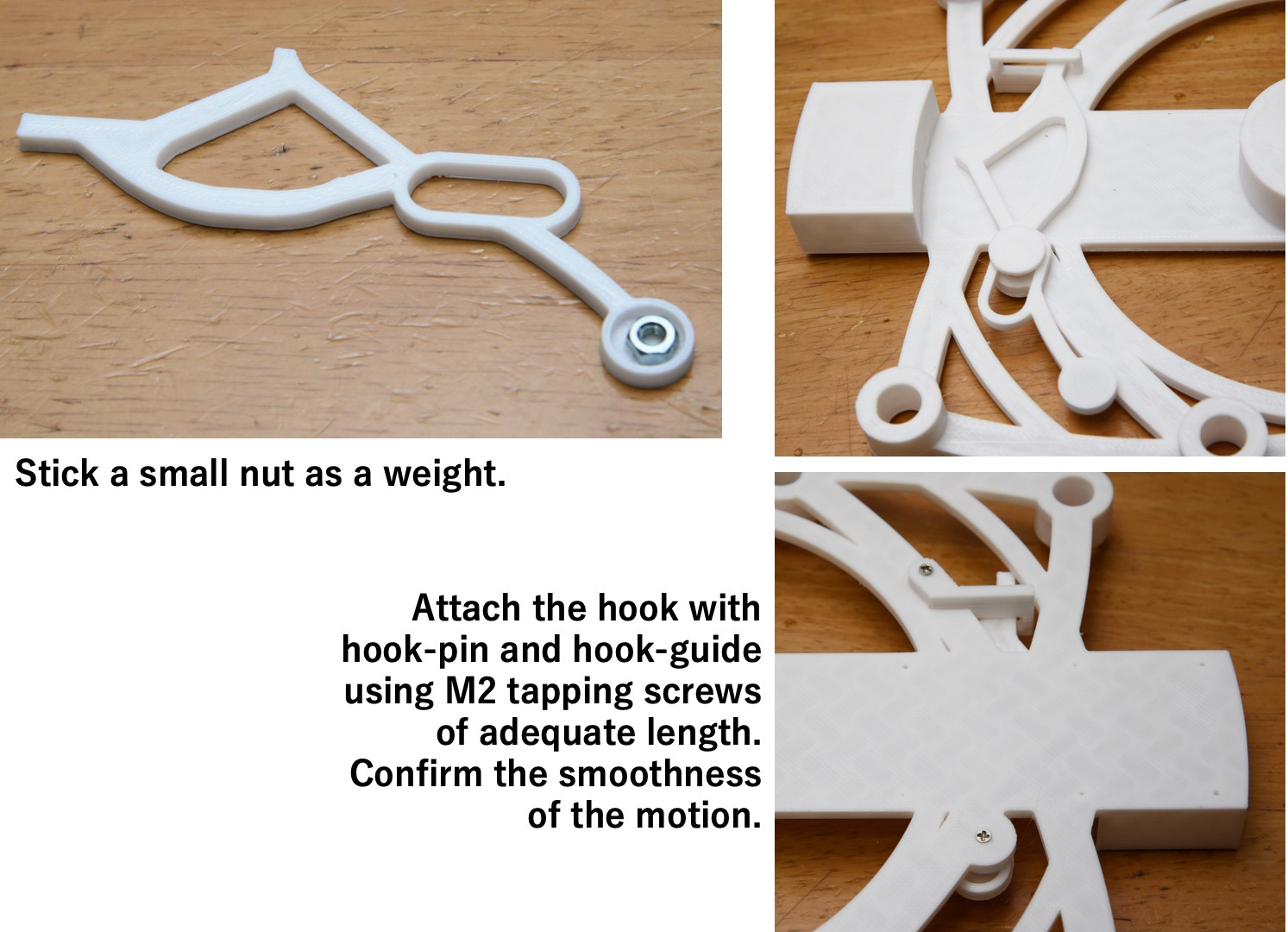
- Stick a small nut to hook as a weight.
- Attach the hook to the frame using "hook-pin.stl" and "hook-guide.stl".
- Please make sure that the hook moves smoothly.
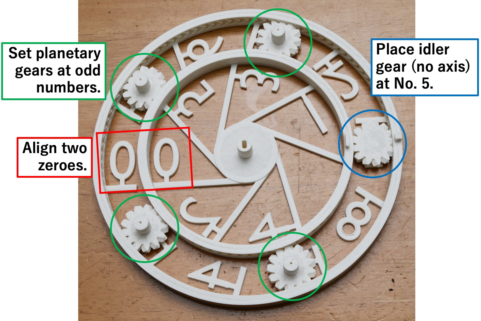
- Place the 1min and 10min rotors upside down.
- Align two 0s.
- Place the gears on the odd numbers. At No.5, use "idler-gear.stl" (gear without axis)

- Attach the frame upside down. Please take a look at the video clip above.
- Confirm the smooth rotation and one-way origin lock mechanism.
- Attach the gear-fix discs to the gears.
- The hour rotor can be assembled in the same way.

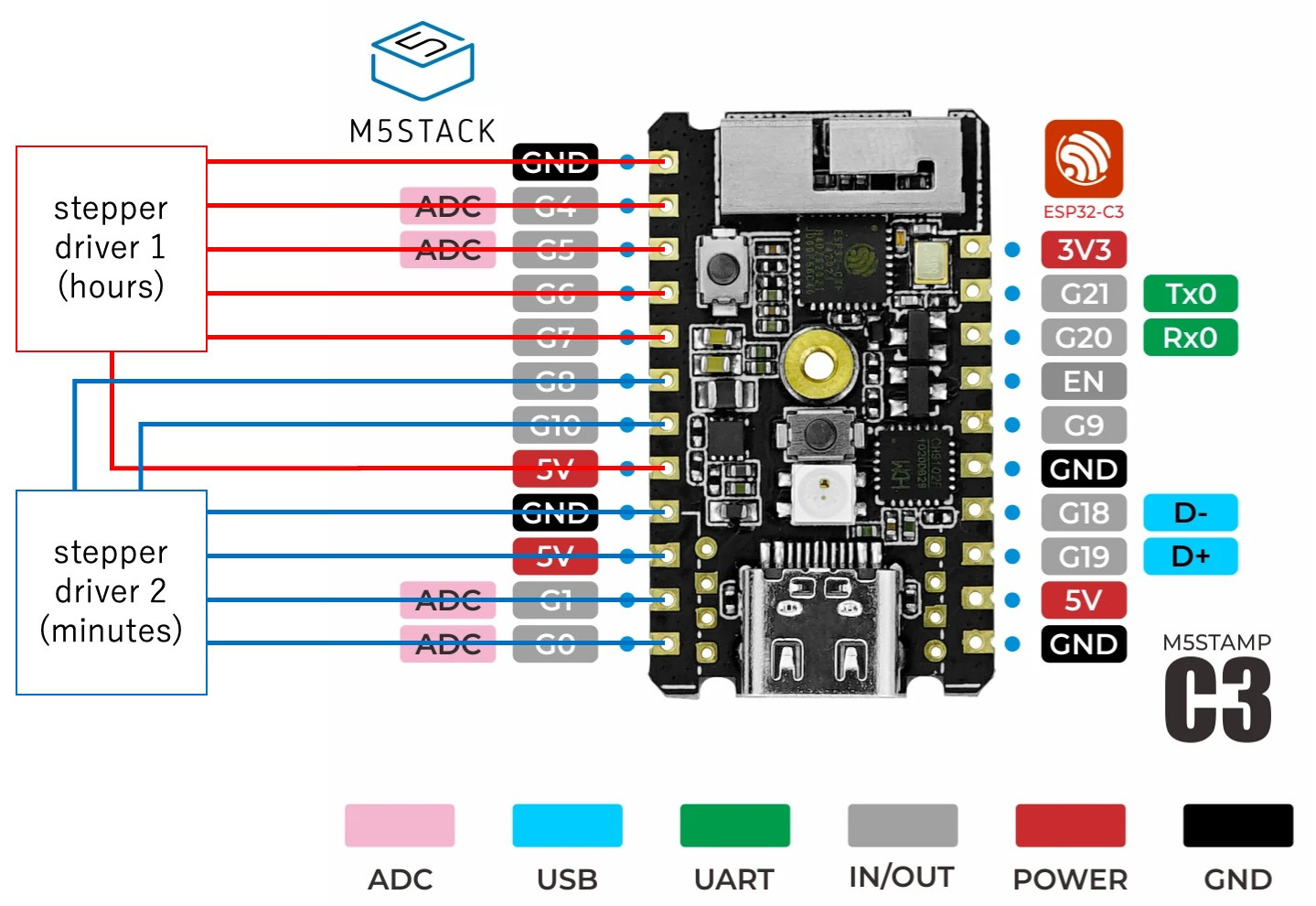
- Attach two stepper motors and driver boards using tapping screws. Use short M3 screws to attach the stepper motor, otherwise M2 screws are adequate.
- Connect micro controller and motor drivers using pin header cables.


- Fix the M5Stamp C3 micro controller to the rear cover using retainer. No screws needed.
- Attach the rear cover to the frame. Use 6 M2 screws with adequate length.
- Hang the clock on a wall. Since the origin mechanism relies on the gravity, it should be upright.
Flash the Program
- Flash the code "clock.ino" to the M5Stamp C3 using Arduino IDE.
- To perform the test, turn on the flag named DEMO_MODE at line #4, as
#define DEMO_MODE true
- Turn off (set to false) the flag above, to acquire current time via WiFi. Set SSID and password in the source code or use SmartConfig feature of ESP32.
- If the motion is not smooth, use lubricants.
Category: Gadgets