
NixieDIY IN-12 Clock Case
Obliczymy ostateczną cenę na podstawie wybranego pliku. Sprawdzisz ją i zaakceptujesz przed płatnością.
Zapisane na tym urządzeniu.

A case for your NixieDIY nixie clock!
- Ocena
- 0 / 5
- Polubienia
- 35
- Pobrania
- 91
- Wydruki
- 0
- Wyświetlenia
- 1561
- Oceny
- 0
Aktualizacja u źródła:
Informacje o modelu
- Źródło
- Printables
- Kategoria
- Electronics
- Licencja
- Creative Commons — Attribution — Noncommercial — Share Alike
*UPDATE 07/21/23: Added “Base” file for angled display
I really enjoyed designing this project and got lost in it for hours much to my enjoyment. I built this IN-12 Nixie clock but it only came with 2 printed feet to hold the PCB, leaving high voltage electronics out in the open for someone to accidentally touch. I have created this guide to show you how I assembled this clock within the case I designed.
The kit I purchased is from NixieDIY. You can either purchase an assembled version or a kit to solder.
Kit: https://www.nixiediy.com/product/in-12-nixie-tube-clock-kit/
Assembled: https://www.nixiediy.com/product/in-12-nixie-tube-clock-assembled/
The assembled clock comes with the tubes installed. Otherwise if just purchasing the kit, you will have to purchase the tubes separately. The best place to look is probably eBay. If you can find them try and purchase New Old Stock (NOS) tubes, as they are “brand new” and not been salvaged out of used equipment.
If you are building the IN-12 kit, the instructions for assembly can be found here: https://www.nixiediy.com/downloads/
Once you have completed the clock and confirm it is working you can the insert it into the case. To do this you will need some additional hardware:
- 4x M3 male-female 20x6mm standoffs
- 4x M3 female-female 10x6mm standoffs
- 4x M3x10 screw
- 4x M3x5 screw
From the print files you will need:
- 1x Clock Face
- 1x Clock Body
- 1x Back Panel
- 3x Button
- OPTIONAL: 1x Base

I printed my parts on a satin sheet to hide the layer lines but also give it a nice finish. All print files are already oriented with supports where necessary.
For assembly, thread together the standoffs through the PCB with the longer ones on the tube side.

Then on the case, slide the 3 buttons into the side wall BEFORE placing the PCB inside the clock body.

Once the PCB is in place the buttons should not be able to fall out. Install the back panel with the 4 M3x5 screws.

Holding the back panel, flip it over so it does not fall out, insert the face plate and screw in the remaining M3x10 screws


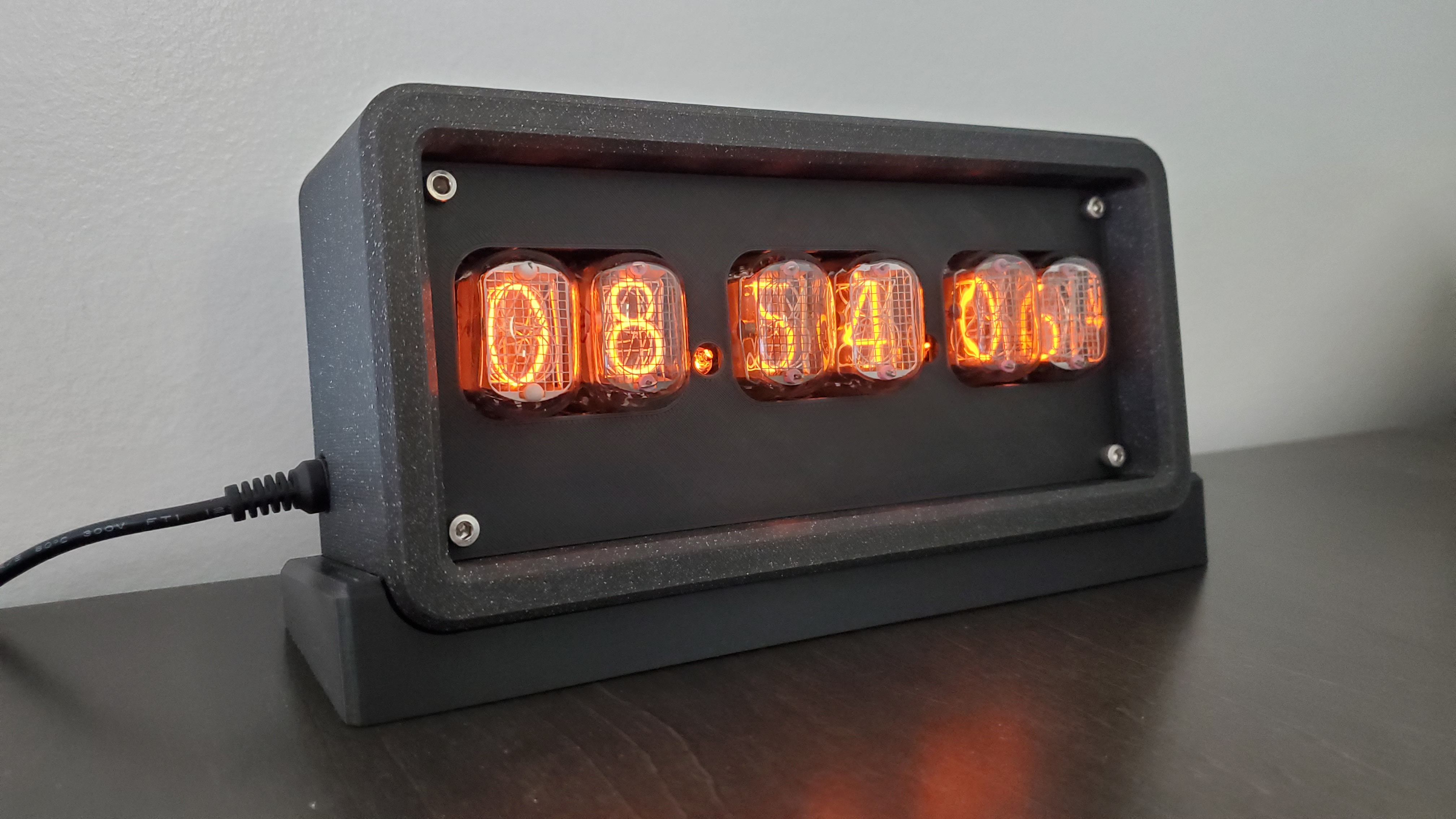
Please let me know if there is anything wrong with the files and if there are any improvements that could be made. I am hoping to design another case in the future alongside another clock build. Unfortunately when designing this I made it for a straight barrel plug and the rear hole is too long for a 90 degree elbow plug to work (unless you have an extension) This may be resolved in a future redesign.