
Combined Gotek and CF-ide in 3.5" disk drive
Obliczymy ostateczną cenę na podstawie wybranego pliku. Sprawdzisz ją i zaakceptujesz przed płatnością.
Zapisane na tym urządzeniu.

I have a Gotek drive and CF-IDE card reader for my Amiga 4000. This fits a standard height 3.5" drive bay.
- Ocena
- 5 / 5
- Polubienia
- 22
- Pobrania
- 202
- Wydruki
- 1
- Wyświetlenia
- 2369
- Oceny
- 2
Aktualizacja u źródła:
Informacje o modelu
- Źródło
- Printables
- Kategoria
- Computers
- Licencja
- Creative Commons — Attribution
I have a Gotek drive and CF-IDE card reader for my Amiga 4000.
As I already use the 5,25” bay for a CD-ROM drive, and one of the 3,5” bay’s for the original Floppy drive, I needed another solution.
My A4000 has a standard height floppy drive, so there is room for two 3.5" drives.
My idea was to try to combine the two in a single 3,5” drive bay.
Print instructions
Printed with a couple of small support enforcers on the front part.
If you want to be creative you could make a filament change so the logos on the front are more visible.
What you need:
- a Gotek drive or just its PCB.
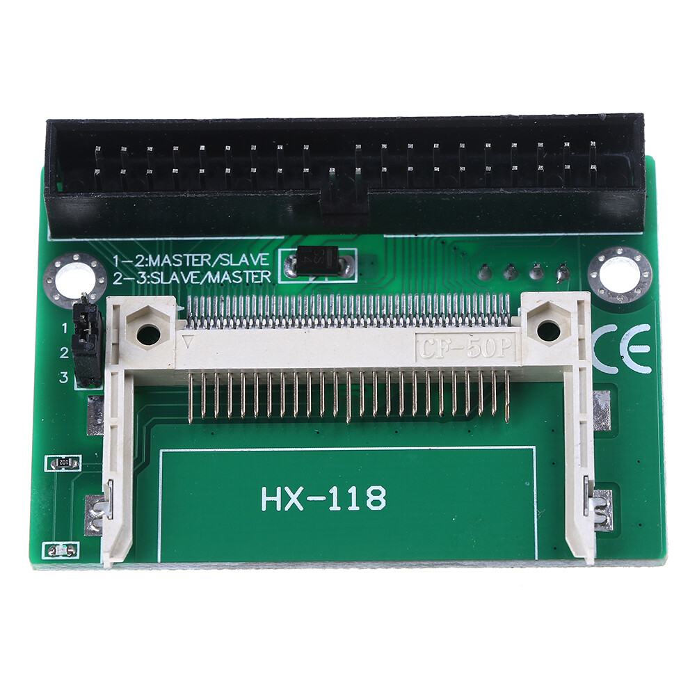
- CF To IDE found on eBay the one I designed for is the one that says HX-118 on the PCB.
- ec11 rotary encoder 15mm. If you want to use that with the Gotek.
- Piezo buzzer.
- OLED display 0.91 Inch 128x32 IIC.
- a bit of wire.
- 8 M3x5 screws.
 |
 | 
| 
|  |
Assembly
Start by disassembling the Gotek Drive


Gotek side by side with the CF-IDE card reader

Remove the breakpoints on the Gotek PCB


Solder an upright pin header, and wires for the LED.
Be careful not to damage the thru-hole vias on the PCB when unsoldering the header.


Remove the supports from the front part.

Assemble front and back using 3 M3x5 screws.


Mount the Gotek PCB with 3 M3x5 screws.


Mount the CF to IDE adapter with 2 M3x5 screws.


Place the Piezo buzzer in the small pocket.


Add the Rotary encoder and the knob.


Now it is ready for the mounting in the case.


Links:
OLED and Rotary encoder connections described Here:
http://llamamusic.com/s50s550/FlashFloppy_GOTEK.html
And Here:
https://github.com/keirf/FlashFloppy/wiki/Hardware-Mods