
Creality K1 - Adjustable z carriage + CAD files
Obliczymy ostateczną cenę na podstawie wybranego pliku. Sprawdzisz ją i zaakceptujesz przed płatnością.
Zapisane na tym urządzeniu.

The print bed can be easily adjusted with this z carriage using an Allen key.
- Ocena
- 5 / 5
- Polubienia
- 349
- Pobrania
- 1276
- Wydruki
- 12
- Wyświetlenia
- 10 805
- Oceny
- 15
Aktualizacja u źródła:
Informacje o modelu
- Źródło
- Printables
- Kategoria
- Creality Parts & Upgrades
- Licencja
- Creative Commons — Attribution — Noncommercial — Share Alike
Change log:
27.03.2024 - Adding CAD step files for download
25.01.2024 - v2 of the carriage is released (no need for the camera holder fix). Use it at least for the right side if you have a camera. You can of course also use it for all sides.
25.01.2024 - Update camera holder fix v7
23.01.2024 - First release published
Please note:
This design is still in the test phase. I am currently optimizing the accuracy of the holes and the sliding guide. At the moment it is still necessary to slightly adjust the movable body with sandpaper so that the guides are tight but still easy to move. The design has been tested in my K1 printer and it works very well. Only the two front carriages are replaced because of problems to change the rear one. But, the rear one is not necessary to bring the printing bed in good position.
Difficulty:
Some manual skill is required for the upgrade. If you are not technically gifted, you should have the upgrade done by a competent person. In the worst case, you could destroy the linear bearings, damage the toothed belt or even bend the threaded rod.
No special tools are required. Some fine sandpaper is required to deburr the corners of the fit and grind them flat so that they fit better. A sharp cutter knife to remove the door seals at the screw points is very helpful. Otherwise, the tool from the printer accessories should be sufficient.
Caution:
The v1 right front z-carriage can touch the camera when the print bed moves all the way up. Use the v2 z-carriage at least on the right side or on both.

Figure 1: v2 z-carriage at 0-position
Description:
Thanks to the wonderful construction of @Thomas White and @Henlor. I had to realize my ideas immediately. :) The main problem in my eyes is the firm connection of the adjustable parts, so that no bad print image comes out. I tried this with the 'dovetail' guide and the first printed parts work very well.

Figure 2: v1 z-carriage test model
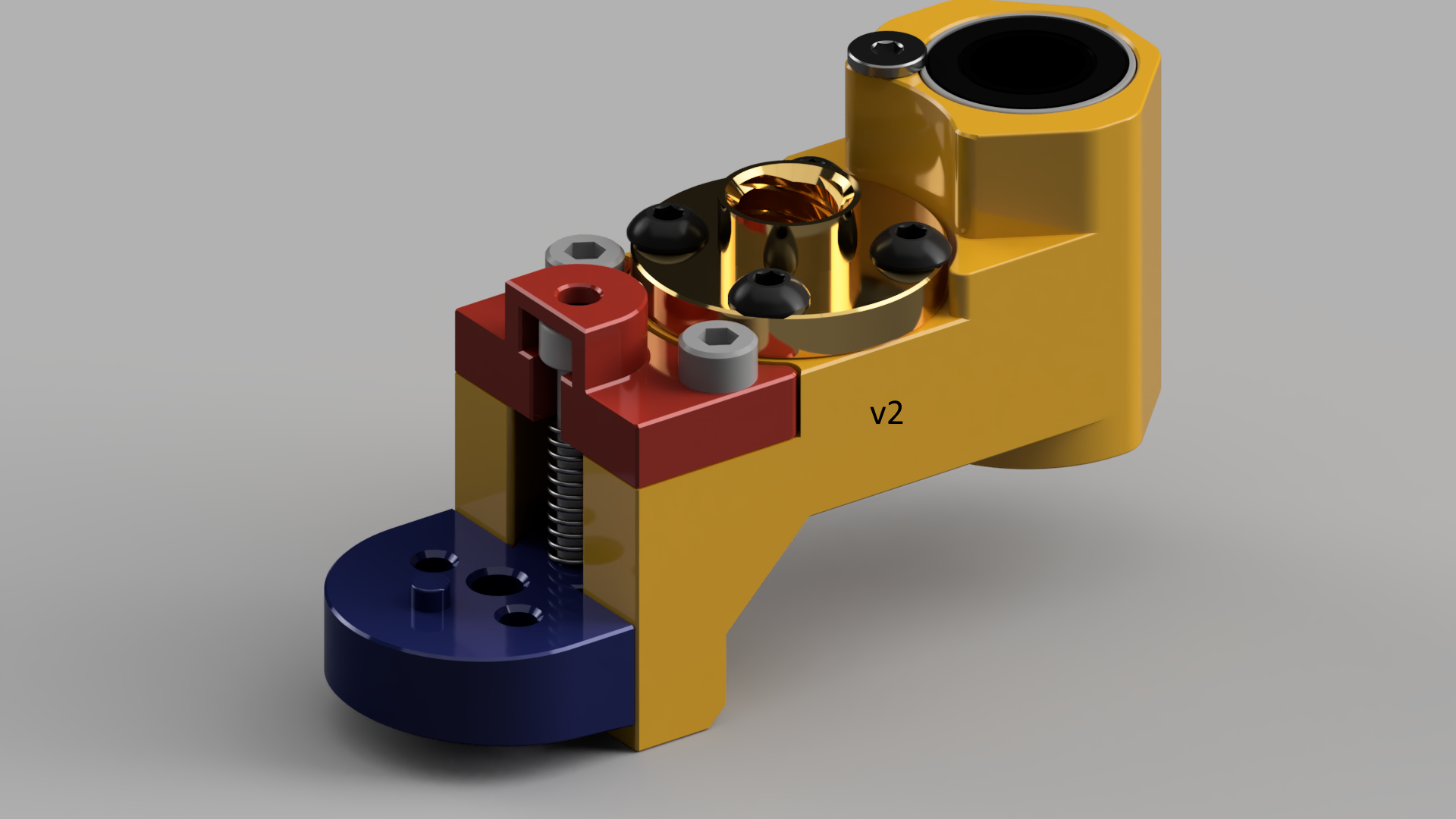
Figure 3: v2 z-carriage CAD model
Printing:
Filament: ASA / ABS
Layer: 0.2 (0.4 nozzle)
Support: Yes
Slicing Tolerance: Exclusive (optional for better size)
BOM for one carriage :
2 x M3x10(12) SHCS (DIN 912)
1 x M3x30 SHCS (DIN 912) (v2 - M3x25)
1 x M3 nut (DIN 912)
1 spring ( optional - i used one from a ball pen)
Assembly:
- After printing, deburr all sharp edges in the carriage area.
- Try to push the slide into the guide. If it is difficult to move, carefully sand the front guide surfaces with sandpaper until the carriage fits in with a little friction. The connection must not be too loose.

- Remove the carriage and insert the M3 nut into the front slot of the carriage. Then push the carriage back into the guide up to about the middle.
- Insert the head of the M3x30 (v2 - M3x25) screw into the cover through the screw slot and slide the spring over the screw.
- Guide the three parts with the screw in front to the hole in the carriage where the nut is located and tighten the screw with an Allen key through the opening in the cover. Turn the screw so far that the cover can lie flat with a little pressure.
- Now screw the lid tight with the two M3x10 screws. I simply screwed the screws into the plastic. If you don't tighten them too tightly, they should hold sufficiently.
It is now possible to adjust the height of the carriage with the Allen key through the small hole in the lid. Seen from the original component, the slide can be adjusted approx. 1 mm further down. Upwards it is several millimeters. Each turn of the screw means 0.5 mm up or down. It is a good idea to start by turning the screw up two turns (1 mm) from the bottom. This is then approximately the position of the original part.
Installation in the printer
Preparations:
- Lower the print bed approximately to the middle.
- Then switch off the printer and unplug it (I left it on because of the light :))
- Remove the two side plastic panels by loosening the 10 screws on each side. Caution: The cable for the large fan is in a short connector on the right-hand side. The side panel can easily be tilted and the plug connection disconnected.
- Dismantle the door.
- Detach the print bed from the three z-slides by unscrewing the two screws at each of the three points. Make sure that the print bed does not fall down when it is half unscrewed. When all the screws are out, lift the print bed slightly and place it on the bottom of the printer.
Left side:
- On the left side, let's start loosening the four screws of the trapezoidal thread - TR8x8-4, so that the carriage falls down.
- Now the upper left Z-rod mounting must be loosened. To do this, two screws must be loosened in the frame. One is hidden behind the left door panel. Use a small knife to carefully remove half of the glued-on plastic strip and then use an Allen key to undo the screw behind it. Please do not press the plastic strip back on firmly until everything is screwed back on. Once the screws have been removed, the monting comes off easily as the belt tension is still acting on the threaded rod at the bottom. It can simply be pulled upwards off the threaded rod.
- Now unscrew the trapezoidal threaded screw upwards from the carriage.
- If you now push the two rods at the top slightly inwards with one hand, you can simply push the carriage out upwards. But be careful, only move the rods enough to remove the carriage.
- Let go of the bars and pat yourself on the back, you've done well so far :)
- Loosen and remove the small locking screw on the carriage that holds the linear bearing in place.
- Carefully try to push out the linear bearing from below with a plastic/wooden rod (<9 mm). I didn't find it very difficult, but you have to press harder at first.
- Now you can insert the linear bearing into your newly printed and assembled carriage and secure it again with the small screw. If it is too stiff, try sanding the fitting hole a little with fine sandpaper (roll it up into a roll). Normally the linear bearing should slide into the fit with a little more pressure.
- Go back to the printer, press the two shafts slightly to the side so that you can slide the new carriage with the linear bearing onto the 8 mm rod. Of course, the threaded rod goes through the other hole. :) Let the carriage slide down.
- Get the trapezoidal thread - TR8x8-4 and turn it onto the threaded rod.
- Use a ruler or similar to measure the height of the TR8x8-4 trapezoidal thread on the right-hand side. Note exactly where you have measured it, as we need the measurement for the left-hand side.
- Turn the TR8x8-4 trapezoidal thread to approximately the measured height and slide the carriage underneath. Then fasten the TR8x8-4 with at least two screws. We will adjust it more precisely later.
- Now the upper z-rod bearing must be reattached to the frame with the two screws. However, the threaded rod must first be guided into the ball bearing and the guide rod into the fitting hole. This is a bit tricky because you only have two hands. It is best to bend the plastic rail on the door frame away slightly and place the two screws and the Allen key within easy reach. Make sure that both rods are properly seated in the bearings. Only then will the frame screws fit correctly. Tighten the bolts firmly but carefully.
- Now we set the correct starting height of the carriage. Take your ruler and check the height of the trapezoidal thread so that it is as shown on the right. Half a millimeter is not important here. If you need to correct the height, loosen the screws from the trapezoidal thread and always rotate it by 90° so that the drilling pattern always fits. Then slide the carriage under the trapezoidal thread and fasten the 4 screws above it.
- Now you can press the plastic strip firmly back onto the left-hand door frame and enjoy your own assembled carriage.
Right side:
Basically, the same steps must be taken as on the left-hand side. I will only go into the differences here.
- The upper right Z-rod mounting must be loosened. The two frame screws must also be loosened for this. The front screw is hidden behind the plastic adhesive strip on the right-hand door stop surface. Using a sharp knife or razor blade, you can carefully cut out a strip in the area of the screw. The position of the screw is clearly visible. Continue as described on the left-hand side 2.
- If you have mounted the K1 camera, be sure to unplug it. You can remove the camera mount before or after. Bear in mind that the camera mount no longer fits well and you will have to print out an extended one.
- After you have reassembled the new carriage, you must adjust the height of the trapezoidal thread again. This time take the measurement on the left-hand side or use the value you have already measured.
Finally:
- Once the two carriages have been replaced and the upper bearings are fixed again, it is time to check the approximate height of the print bed support surfaces once more. The height of the new carriage support surfaces can now be adjusted with an Allen key for precise adjustment.
- The print bed can then be carefully lifted at a slight angle and placed on the bearing surfaces. Make sure that the small round pin fits into the hole. Now tighten the six screws of the print bed again.
- Before the side panels and the door are refitted, a first functional test can now be carried out. Switch on the printer and move the print bed to the home position. If strange noises occur when turning the z-axes or if something does not work, switch off the printer immediately and try to find the error. Normally, the print bed should move up and stop at the home position.
- If everything went well, screw the side panels and the door back on. Don't forget to plug the cable for the large fan back into the connector. You can also fit the camera mount while the right-hand side panel is off.
The modification is complete. Congratulations to you!
Print bed leveling:
Now it is time to level the print bed. I just jumped in at the deep end and calibrated the print bed using Mainsail/Heighmap. As expected, the result was a print bed that was twisted by 1.5 mm. I adjusted the new carriages until I finally had a maximum deviation of 0.092 mm. I have to say that I attached a cleaned glass plate to the print bed. I don't know whether the glass plate or the gantry is warped.


Good luck!