
3D Printer CPAP Turbine General Mount Prototype - Resmed S10/S9
Obliczymy ostateczną cenę na podstawie wybranego pliku. Sprawdzisz ją i zaakceptujesz przed płatnością.
Zapisane na tym urządzeniu.

Part cooling fan using a Resmed S10/S9 turbine. Prototype designed to attach to 20mm extrusions.
- Ocena
- 0 / 5
- Polubienia
- 8
- Pobrania
- 26
- Wydruki
- 0
- Wyświetlenia
- 819
- Oceny
- 0
Aktualizacja u źródła:
Informacje o modelu
- Źródło
- Printables
- Kategoria
- Voron Parts & Upgrades
- Licencja
- Creative Commons — Attribution
I had access to old used Resmed Airsense s10 CPAP machines that I tore apart to get to the turbine.

Turns out they are these compact cylinder units which I have not seen any mounting mechanism for. It is a 3 phase without hall effect, but still seems quite powerful, though documentation is scarce on a part that has no part number documented. I included screenshots of what I could find.

So I designed one of my own, if rudimentary, mounting hardware. I would recommend only salvaging these motors from an existing dead unit instead of purchasing them, as they seem quite expensive as stand alone parts for purchase. Check out iFixit for disassembly info:
https://www.ifixit.com/Guide/ResMed+AirSense+10+Pump+Motor+Replacement/137050
The turbine is encased in a plastic shell, and a blue silicone sock. The shell was too oddly shaped and no practial mount points. The sock was also oddly shaped, but I figured some areas of its shape would still contribute to mounting the turbine, with the added benefit of being a shock absorber. I trimmed either end off the sock as the extended shapes were not useful.
I created a shell that can clamp around the turbine and the silicone sock alone will provide plenty of grip to keep it from moving.I had to include a small notch in the side, to allow the wire retainer space to stick out without getting crushed.
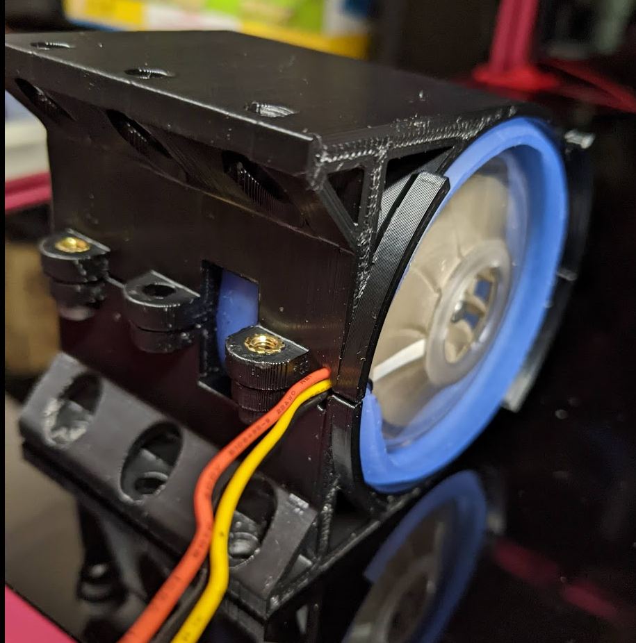
It is a small plastic clip that sits on the side of the housing that holds the three wires. I could have removed it, but I think it should help with strain releaf of the wires. I also included a small notch between the shell parts for the wires to thread lead out.

One side of the unit accepts the M3 5x4 heat inserts, while the other M3 8mm bolts. I made three holes available, but two seemed to work just fine.

The housing can be attached to 20mm extrusions using two or three M5 bolts.
I created a filter mesh, which mainly exists just to hold filter material so it doesn't collapse under the vacuum. Foam or air filter fibre material would work fine, as the only purpose is to protect the turbine from large dust and hair.
The filter housing is removable without undoing screws. I fixed the filter material to the housing using rubber bands. I also included a hose adaptor instead, if there is another filter method preferred, but some kind of filter is Strongly recommended. This turbine cannot be disassembled for maintenance.
I found that the turbine performed well and is very manageable. When linked with a BLDC controller and the PWM signal from a servo pin, I could run the motor from 2%-100% without issue. Only at 1% it would stall which is quite impressive. Since the turbine was basically free, not a bad outcome.
It is not pretty or elegant, but it works. I have uploaded the STEP file for further tinkering.
Strongly suggest printing in ABS.