
Long's Foldback Active Pedal. Compact Force Feedback Active Pedal for Sim Racing (283mm long)
We calculate the final price from your selected file. You review and accept it before payment.
Saved on this device.
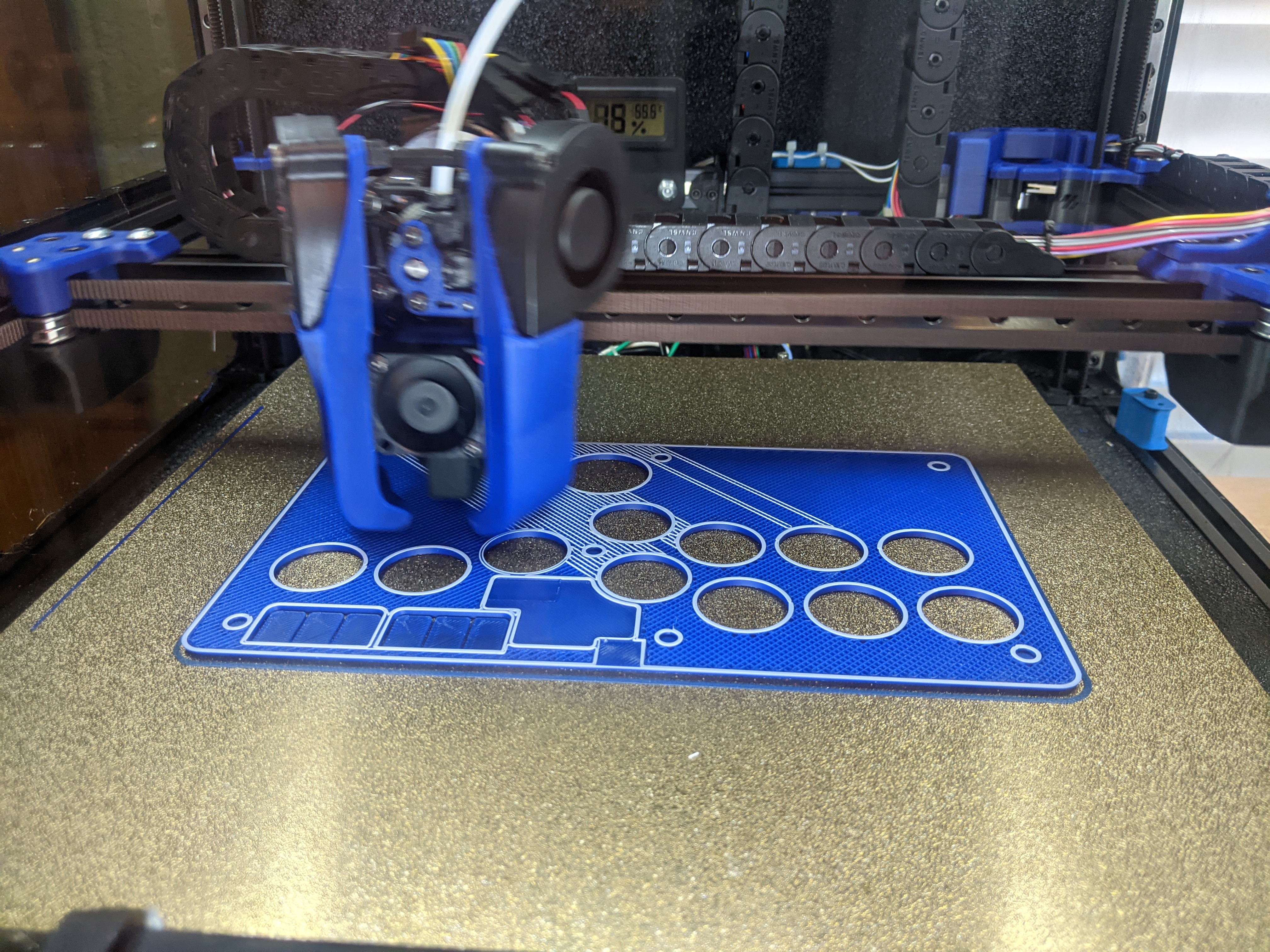
This is a compact, force-feedback active sim-racing pedal with total length 283mm.
- Rating
- 0 / 5
- Likes
- 59
- Downloads
- 201
- Makes
- 0
- Views
- 2,427
- Reviews
- 0
Updated at source:
Model information
- Source
- Printables
- Category
- Video Games
- License
- Creative Commons — Attribution — Noncommercial
****************** Long Shaft Servo Discontinued ******************
The long shaft servo was discontinued :(.
I removed the alpha 0.1 printable mount for the short shaft motor as it didn't work.
I'm working on a new mount that shifts the servo forward a little bit and uses a CNC machined servo/linear actuator mount (~$30 to CNC at JLC). I'm also going to make a few quality of life changes while I'm at it on the underside access to the servo wires.
Intro:
Pedal Overview Video(see the Assembly in the Fusion 360 viewer: https://a360.co/4nbuOvA)
Overview
This is a force-feedback, active sim racing pedal (please visit the DIY FFB Pedal Discord) that is designed to require the least amount of depth. It uses a “stacked” designed where the linear actuator and servo motor are on top of each other and connected with a belt to minimize overall pedal depth.
Long's Foldback - 283mm long
Simucube Ultimate - 415mm
Moza Active Pedal - 382.5
Cost
I built these pedals for $530 dollars each in the US. It really depends on how much you get hit by the tariffs. The tariffs from JLC can be pretty steep.
Features/Design Goals
Rigidity and overall pedal length are #1 priority
Servo can handle max force ~150kg using 5p linear actuator. I've tested to 100kg short term.
Belt driven design with 10mm belt width with 3mm teeth
~69 mm of travel measured from the middle of the pedal
Simucube 74, Moza 49
I generally only use ~30 mm and use the rest of the range to position the pedal
Mount available for Dayton Audio TT25 pedal shaker if you want to use both active pedal and a pedal shaker.
Minimize any metal pieces that are needed and limit to simple laser cut parts
Tensioner to eliminate backlash in the belt system
Support for the servo shaft.
Since we are applying tension to the servo shaft with the belt, the shaft benefits from being supported on the end after the pulley.
Current Limitations
Increased cost/complexity. Obviously with a drivetrain it's going to have more components and complexity.
Noise in the drivetrain.
I currently get some squeaking in the drivetrain. I can't figure out where it's coming from yet, but I don't notice it when I'm driving.
Changelog:
2026-09-09
Updated the pedal arm and pedal face to v1.2 after a pedal arm breakage.


I had a pedal arm breakage along the right angle (red arrow) on the sk8 mounting surface.
s. Version 1.2 makes the pedal 10mm wider and removes the stress point. Also added a spot for optional 3rd heatset and m5 x 40mm bolt so that the pedal face reinforces the joint more also.
2026-08-23
Added alpha v0.2 files for compatibility with the short shaft isv57t.
Thanks to Juliscreudo for collaborating with me on this.
This utilizes a CNC servo/linear actuator mount. Plugging this into JNCCLC shows a cost of <$30. CNC is needed here because you need the pulley to be as close as possible to the servo.
This requires (4) m5 nuts and (4) m5 x 16mm button heads. The servo is now bolted from the front and secured behind the servo with the nuts. Please see the CAD if you're confused.
2026-06-06
Take project out of beta! Change all versions to 1.0. Note that no files have actually changed except the bellows.
The bellows were adjusted very slightly to make it a little easier to print. It's still a tricky print, but this should help a little.
2026-2-3
Change recommendation for rail pitch to 5p for all.
Note all 3 original brake pedals have been working perfectly, including the one being used at 90kg.
2025-10-01
Updated some of the Brass heatset counts. Thanks to lukas for the heads up!
it should be 18 M4 x D6 x L6 heatsets.
2025-09-27
Added [Pedal - Arm v0.93.stl]
Added lower indexing slot so that the pedal face can be installed into the lower position.
Thanks to Lukas on discord for bringing this to my attention :)
Updated CAD to v0.93 to reflect this change.
2025-09-22
Added information regarding setting up the simhub plugin.
Added information regarding modification of the servo to be low profile.
2025-09-18
Pedal arm spacer v0.92 - change ID to 8.1mm
Added notes regarding printing the pedal arm/linkage
Add notes for using a shoulder bolt for the smooth idler.
2025-09-17
Added CAD v0.91 - 2025-09-17
2025-09-14
Added Tensioner - Idler Spacer x2 v0.91. Increase diameter slightly.
Added SK8 Drill Template v0.9.
Update bolt/brass heat insert photos. I incorrectly had bolts labelled as SHCS when they should have been BHCS.
2025-09-12
Update build guide to v1.2. (had some incorrectly labelled bolts)
2025-9-8
Add Case - Gilphilbert V2 v0.91. Increased size of exit hole for load cell wires.
Added Mount - Motor and Actuator v0.9
Added Lower Actuator Mount v0.9
Added the modified servo case cover (modified from Yves Design to use Microfit 3.0)
Pedal - Arm v0.92. Added a stop for the m5 heatsets that the sk8s use so they don't get pulled into the arm.
Added notes on the laser cut pieces.
changed version number on the DXFs to 0.9 as they were incorrectly v1.0
2025-9-7
Pedal - Arm Spacer v0.91. Increase ID and add inner chamfer(was too tight). V0.91.
Pedal - Arm v0.91. Increase ID of hole for F698 bearings by 0.05mm.
Acknowledgements:
DIY FFB Pedal Discord (click here)
captainchris, tcfshcrw, gilphilbert
These guys are the superstars of this project. They write the software and do a ton of work developing the pedals and troubleshooting. Gilphilbert designed the PCB which I'm using in my build to control everything. Without these guys, none of this would be possible. Thanks so much to them!
Also, many other people have built pedals in different styles and contributed ideas and build experience as well. All of these people have built up this community and made it an amazing place. I have learned much from their build logs that I have tried to implement and improve upon in my own build.
ChrisJamesChamp deserves mention as his github writeup was extremely informative and I referenced his guide quite a bit. I also used a version of his Meanwell PSU housing.
Here is the Wiki (https://github.com/ChrGri/DIY-Sim-Racing-FFB-Pedal/wiki) for the DIY FFB Pedal project Lots of info explaining how FFB pedals work and some of the choices made during the build process.
This design was inspired by ZZY's “Foldback” build, which was inspired by Kold's “The Stack.”
ZZY made his design which was functional using CNC metal and carbon fiber. He kindly shared his CAD with me as inspiration for my own build.
I took ZZYs design and remade it from the ground up with the goal of using mainly 3d-printed parts. Added a lot of refinements and improvements like the tensioner, servo shaft support, and the bellows cover for the linear actuator.
Yves designed the original Servo Case pieces that convert the servo into a low profile design. It used JSTs. I modified his concept to use Microfit 3.0.
***************************************************************************************************************
BOM:
Parts from JLCMC.COM | ||
Qty | JLC Model Number | Notes |
1 | JKK60B-5-P-150-A1-H0 |
|
1 | CBTM-34-S3M100-A-D-d8 |
|
1 | CBTT-E1-S3M100-34-E-d8 |
|
1 | CBUJ-N-2-W15-D20 |
|
1 | CDTC-P1-S3M-100-231 |
|
Miscellaneous Parts | ||
Qty | Item | Notes |
1 | iSV57T-130 (non-S) |
|
12 | m3 x D5 x L4 Brass Heat Insert |
|
12 | m4 x D6 x L4 Brass Heat Insert | |
18 | m4 x D6 x L6 Brass Heat Insert |
|
14 | m5 x D8 x L7 Brass Heat Insert | https://www.aliexpress.us/item/2255800046675771.html Need one additional if using the m6 shoulder bolt for the idler tensioner. |
2 | m6 x D8 x L7 Brass Heat Insert |
|
4 | SK8 Shaft Support | |
7 | 698-2RS Bearing (ABEC 9) | |
1 | DYLY-107 (200kg) Load Cell | |
2 | m8 x 45mm Shaft | |
1 | m8 OD pin with m5 internal thread, 75mm length |
|
1 | Gilphilbert PCBA V2 |
|
1 | Meanwell LRS-350-36 |
|
1 | XT-30 Male |
|
2 | Optional m5 cup head washer |
|
Bolts | |||
Size | Qty | Item | Notes |
m2.5 | |||
| 4 | m2.5 x 5 x 8mm SHCS | Attach Linear Actuator Cover |
m3 | |||
| 16 | m3 x 8mm SHCS | button head or socket is fine |
| 2 | m3 x 16mm BHCS | button head to match the rest of the fasteners on the side panel |
m4 | |||
| 10 | m4 x 8mm BHCS | side panels (lower row) to [plastic base - upper] |
| 24 | m4 x 12mm BHCS |
|
m5 | |||
| 8 | m5 x 12mm SHCS | Attach Linear Actuator to Lower Actuator Mount and attach SK8 Shaft Support to Linear Actuator. |
| 4 | m5 x 14mm SHCS | Servo to Motor Mount. I wrote it as (4) m5x15 SHCS to simplify things, but Ideally, use (3) m5x16 SHCS and (1) m5 x 14 SHCS in the bolt hole behind the tensioner idler. |
| 7 | m5 x 16mm BHCS | Attach Baseplate - Upper to lower baseplate. |
| 6 | m5 x 25mm SHCS | Attach [Pedal - Face] to [Pedal - Arm]. Attach (2) SK8 shaft support to [Pedal - Arm] |
m6 | |||
| 2 | m6 x 40mm SHCS | For the tensioner mechanism |
m8 | |||
| 2 | m8 x 16mm SHCS | Mounting load cell to linkage arm |
***Optional*** m6 Shoulder Bolt | |||
| 1 | Socket head shoulder bolt - m6 shoulder, 30mm shoulder length, 10mm thread length, m5 thread | https://boltdepot.com/Product-Details?product=14234 Used for alternative mounting of the smooth tensioner idler. Will need one additional m5 x d8 x L7 brass insert. |
Printing
*********VERY IMPORTANT! BE AWARE OF MATERIAL SHRINKAGE!*******
We are printing large parts that need to mesh with metal components. These are large printed pieces, so if you don't compensate for shrinkage, your prints will not line up.
To determine shrinkage, print a long piece then measure the length after it cools down.
Approximate Material Shrinkages:
ABS/ASA shrinkage ~ 0.58%
Prints require no supports unless noted in the filename. Print them in the provided orientation.
The only piece currently requiring supports is the Servo Case.
Highly recommend using at a minimum ABS/ASA
Exotic and carbon fiber filaments aren't really necessary. May see some benefit with these filaments with the side panel or with the [baseplate - upper] (that connects mounting baseplate to the side panels).
Perimeters/Infill
For the Baseplate/Side panels/structural pieces
0.4mm perimeters, 0.2mm layer height.
I recommend at least 6 perimeters with 7 top/bottom layers and 45% infill.
For Pedal Arm and Linkage Arm
I recommend using at least 7 perimeters/10 top & bottom layers/ 45% infill.
My friend, who is using 90kg of max force broke his pedal arm that was printed at 5 perimeters/5 top & bottom/25% infill.
Build area of 250x250 minimum
Bellows
I printed this in TPU, but I think this should work with any flexible filament. I bet it would be fine in Nylon, or Polypropylene. It might even work with ABS and PETG.
The key thing is to force your slicer to print the bellows portion of the print using a single line (the bellows portion is 0.5mm wide). The only time I've had issues printing this is when the slicer tires to do very thin lines instead of a single 0.5mm line.
Laser Cut Pieces
I have provided DXFs for side panels and for the baseplate to be laser cut.
Baseplate
Highly recommend you use the metal baseplate.
6.3mm mild steel (if you don't use freedom units, 6mm or 7mm is fine).
4.2mm holes need to be tapped to m5.
Powder coating recommended to prevent rust.
Side Panels
Time will tell, but I don't think these are necessary. I am currently using plastic side panels and the pedal feels very rigid. One of the pedals with plastic side panels is currently being used at 85kg brake force and is holding up nicely.
≥4.7mm aluminum or mild steel is fine. Mild steel will be more rigid, but needs to be powder coated or anodized.
I have added 0.3mm to the hole diameter on the powder coat DXFs.
There are a lot of bolt holes in this piece, so if you powder coat it, be sure to use the powder coat DXFs.
I made a rough guess based on the guidelines from Sendcutsend on how much bigger the holes need to be, but since I haven't actually had powder coated side panels made, I'm not sure if the amount is correct.
On the baseplate that I had powder coated, 8.4mm holes ended up about 8.2mm, which would seem to indicate 0.3mm is enough.
Assembly
Please refer to the CAD or fusion 360 assembly.
Build Guide
Brass Heat Inserts and BoltsSHCS = Socket Head Cap Screw. BHCS = Button Head Cap Screw | |
Heat inserts have to designed so that they are being pulled INTO (vs being pulled out) the part when possible. | |
 Motor Mount Note the front/back orientation of the mount. This is the front side. Back side has ribs on the side that align the servo. |  Baseplate - Upper |
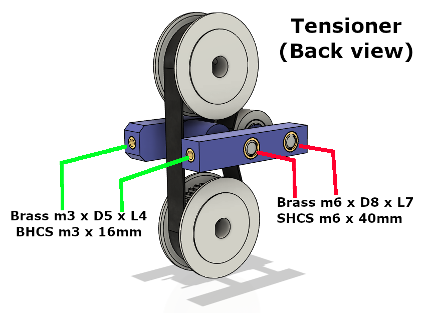 Tensioner (m6 bolts for both) Don't forget spacers on both sides of the smooth idler. |  ***Optional*** - Tensioner (one m6 bolt and one m6 shoulder bolt). Theoretically a better way to mount the idler. Not sure if it really makes a difference though. Note orientation of the m5 heat insert (comes in from the front side). Don't forget spacers on both sides of the smooth idler. Fully tighten the shoulder bolt on the the brass heat insert. |
 Servo Dbl Shear |  Pedal |
 Back Cover |  Lower Actuator Mount |
 Side Panel - Right Left panel is the same |  PCB Case |
Modification of iSV57T-130:
The iSV57T-130's wires come straight out the top of the “sidepod.” Because of this, it would require the pedal to sit around 1 cm higher and raising the pedal face even higher than it already is.

To avoid having the pedal sit super high, modifying the servo sidepod is needed.
If you are ok with the pedal sitting high, you can make the baseplate thicker. I haven't done this, so I'm not sure how much thicker it would need to be.
ChrisJamesChamp made an excellent writeup on modifying the servo. Please refer to his guide for desoldering the connectors and adding new wires.
**note, I used 18g wiring for the main power because I couldn't get 16g wires to fit in the through holes.
If you go this route, I have a modified lid if you don't want holes.

Lid (non-modified housing) with support.stl
Modified servo housing
I have my own version (based on Yves design) to reprint the Servo Plastic housing which adapts it to using micro-fit 3.0 connectors.


If you go this route, I recommend using the version where the latches of the micro-fit face away from the servo so they're more easily accessed from the bottom of the pedal.
Two ways to print this housing.
upright with support

No supports, rotated 45 degrees.
Rotate the part 45 degrees, then cut ~2mm off the bottom so it has a flat surface for the build plate.

Power Supply:
Check out ChrisJamesChamp's PSU mounting. There's several ways out there, but his is pretty nice.
https://github.com/chrisjameschamp/DIY-Active-Pedal-Design/wiki/03-%E2%80%90-Power-Supply-Unit
Setting up SimHub/SimHub Plugin:
Please refer to the Wiki (https://github.com/ChrGri/DIY-Sim-Racing-FFB-Pedal/wiki/Complete-the-software) for setting up the software.
Latest plugin (stable release) is located at https://github.com/ChrGri/DIY-Sim-Racing-FFB-Pedal/releases
SimHub Plugin Settings | |
 |  |
 |  |
 |  |
Flashing Firmware to the Gilphilbert V2 board:
The web flasher is located at https://gilphilbert.github.io/pedal-flasher/
I'm using the development releases. Here are my settings.

Note, to use development releases you need to update the simhub plugin via the link in simhub from the stable to the development release.

Important Links:
FFB Pedal Wiki
Simhub Plugin Releases
Web flasher to program control board