
Big Knob Portable CW Morse Code / Telegraph Key
We calculate the final price from your selected file. You review and accept it before payment.
Saved on this device.
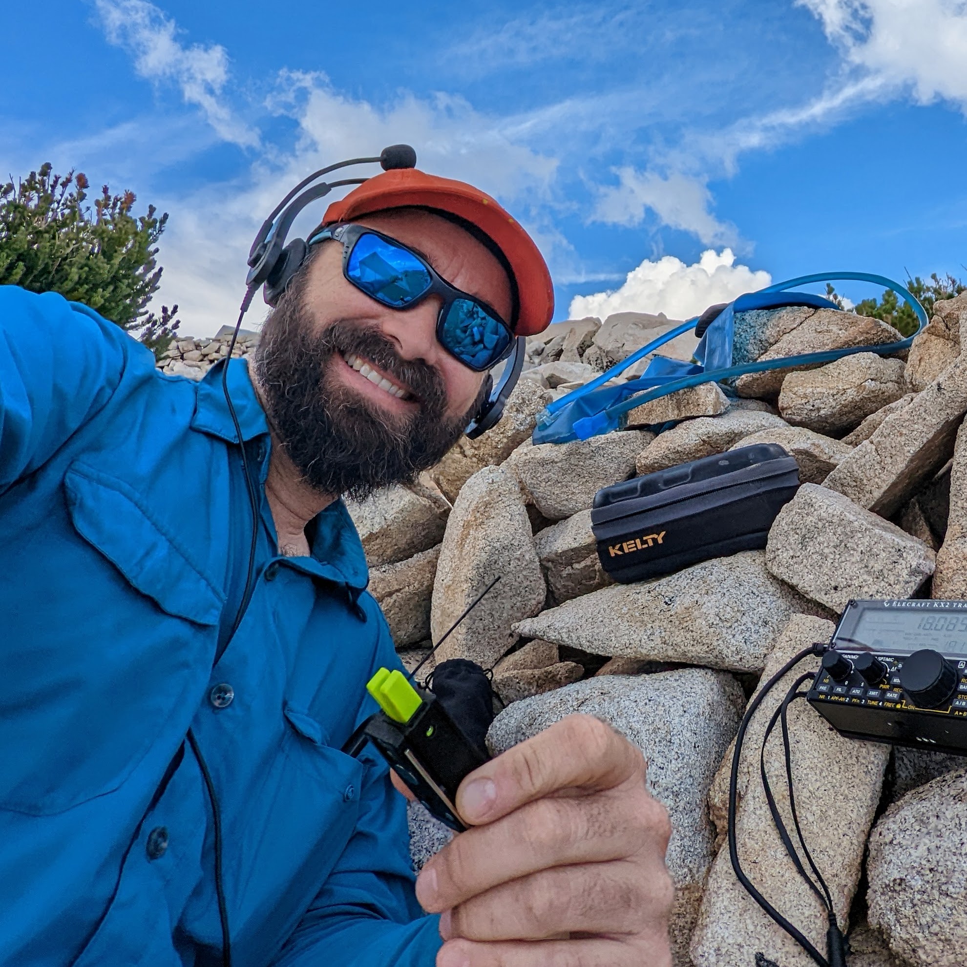
Less compact, but functional than the ultra-portable version of the key.
- Rating
- 5 / 5
- Likes
- 32
- Downloads
- 269
- Makes
- 1
- Views
- 2,069
- Reviews
- 1
Updated at source:
Model information
- Source
- Printables
- Category
- Other Gadgets
- License
- Creative Commons — Attribution — Noncommercial — Share Alike

BACKGROUND:
As an avid portable HF operator, regularly activating SOTA summits and parks for POTA, and an SKCC member, I wanted a fun little straight key to fit in the smallest possible kit. So I made one… then I modified it for better usability.
For portable ops, or to mount it to board for desktop operation, consider also printing the base as well. If you want an even smaller version, try out my one-piece key https://www.printables.com/model/430014-ultra-portable-cw-morse-code-telegraph-key
Parts are kept to a minimum, and total cost per unit for a batch of 10 is less than $2 each! At 60 x 23 x 10 mm (2.3 x 1 x 0.4 in.), this little guy won't take up much space in your pack, but provides adequate performance. Set screws allow independent adjustment of the throw and tension/resistance of the key. The 3.5mm TRS jack allows connection to your radio with any standard Aux cable.
Holes to press in three 4 mm magnets into the base of the key, and holes for 10mm magnets in the base plate/leg strap provide many options for mounting and use.
BILL OF MATERIALS:
Links are Amazon Affiliate links - It costs you nothing more, but I get a few cents on the dollar from Amazon if you purchase through these links.
| Mandatory Items | Qty | Source |
| 3d Printed 2 Piece Straight Key Lever | 1 | Print it using the attached STL |
| 3d Printed Knob | 1 | Print it using the attached STL |
| 3d Printed Base | 1 | Print it using the attached STL |
| 3d Printed Case | 1 | Print it using the attached STL |
| 3.5 mm TRS Panel Mount Jack | 1 | https://amzn.to/3Hadrd2 |
| M3 x 4 mm Set Screw | 3 | https://amzn.to/3ir8Mca |
M3 x 8 mm Machine Screw (Alternate: Use one additional M3 x 4 mm | 1 | https://amzn.to/3TMV5Tr |
30 ga Silicone Copper Wire (Alternate: NiCr wire from my other | 30 mm | https://amzn.to/409le1s |
| PETG Filament | ~20 g | https://amzn.to/3H9QN4p |
| Additional/Optional | ||
| Aux Cable (4 ft) | 1 | https://amzn.to/3XZ1IUo |
| 10 mm x 2 mm Magnets (for the base) | 2 | https://amzn.to/3VYIxIp |
| Silicone Rubber Pads | 4 | https://amzn.to/3LKvWa7 |
| Leg Strap | 1 | https://amzn.to/40EgO2u |
TOOLS:
- 3d Printer capable of printing PETG
- 1.5 mm hex driver (https://amzn.to/3gX4sB8 or https://amzn.to/3ulV3X1)
- #1 Phillips head screwdriver (https://amzn.to/3HaQlD2)
- Tweezers (https://amzn.to/3BaOeex)
- Wire cutters or scissors you aren't worried about damaging (https://amzn.to/3VycZJK)
- Soldering iron (optional - you can build the paddle without this) (https://amzn.to/3P3bxgk)
ASSEMBLY:
1.) Print all the things.
I've included the GCode I use on a Prusa i3 Mk ii if you want to just download and hit “print.”
Print your parts for the assembly. Use PETG only! This design relies on the flexibility and elastic deformation capability of PETG. PLA will not work.
The attached gCode uses default Prusament PETG settings and .3 mm layer height.
Supports should not be necessary for any of the prints.
You may need to clean up the openings of the bottom holes on the base plate to get the magnets in if your first layer height results in some elephant's foot spreading.
2.) (Optional) Press the 4 mm magnets into the base.
CAUTION: Applying too much pressure to the top lever may break the key. Heat the holes with a heat gun or soldering iron briefly if they are too tight.
Place the 4 mm magnets on a flat magnetic surface. Align a bottom hole of the straight key frame to the 4 mm magnet and carefully press into place. Repeat for each hole and magnet.
3.) Attach a 50 mm (2 inch) piece of wire across both side lugs of the 3.5 mm jack.

Do not attach wire to the ground (center) lug. Use only 26 ga or smaller wire.
CAUTION: Do not overheat the lugs or it may damage the connector. Solder the wire to each of the short lugs.
If you don't have a soldering iron, twist the wire onto the lug, securing it through the hole and wrapping strand around the lugs. Try to make good electrical contact.
4.) Attach another 50 mm (2 inch) piece of wire to the long (ground) lug of the 3.5 mm jack.
CAUTION: Do not overheat the lugs or it may damage the connector. Solder the wire to the ground lug only.
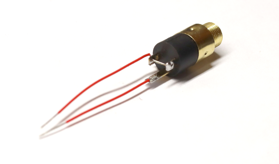
5.) Measure and trim the wires to the length shown below.

Place the 3.5 mm jack on the straight key and trim the wires even with the end of the key when the jack is in placed in the approximate final mounting position.
Strip about 5mm of insulation from the end of each wire.
5.) Insert the wires into the holes as shown.

Ensure wire ends go into holes. Insert them all the way in and look to verify the wire strands are visible from the top and bottom of the key in each hole. Use tweezers to help them into place if needed.

Place the threaded portion of the jack into the rear hole. Secure with the nut.
Install the M3 set screw for spring tension adjustment as shown. Start with the spring tension set screw flush with the bottom of the straight key lever and just begins to contact the spring.

6.) Install the bottom set screw to capture the wire from the bottom.

Screw in the set screw until it extends .5 - 1 mm into the gap under the lever.
Once in place, trim any strands of wire that get pressed out into the gap using flush cutters or a razor blade.

7.) Install the M3 x 8 machine screw into the “knob” of the key.

Align the hole in the knob with the spring tension set screw.
Alternatively, install the M3 x 4 set screw in the hole, protruding .5 - 1mm from the bottom of the lever, then install the knob with the M3 x 4 machine screw to secure the knob.
8.) Install the return stop set screw.

Screw in the return screw to give about a 1 mm gap under the screw when the key is compressed. This screw helps adjust the throw of the straight key.
9.) Prepare the base-plate/leg strap.

Press the 10mm magnets into the center holes of the base plate.
Place silicone rubber pads in the four outer corner holes of the base plate.

Lightly sand the key holder lug inner surfaces to optimize fit and level of grip.
(Optional) Install the elastic leg strap.
10.) Adjust for optimum feel and get on the air!

Updates:
2024-01-15: Revised the flat-folding knob cover to allow the key to slip in a little easier, and to protect the whole key.
CAUTION:
Because this paddle relies on flexing plastic for the hinge, it has certain failure modes that make it easy to break if you apply force in the right spots. DO NOT press side to side on the lever. The large-knob version doesn't work with the cover/case, but the folding knob design does. Use it if you want to carry it in a pocket or pack without breaking it.
THANKS:
Thanks for building this straight key. I hope to get you in the log some time while you're using it.