
Voron 0.2 - LazyCams - Tool Free Locking Idlers (for Top hat))
We calculate the final price from your selected file. You review and accept it before payment.
Saved on this device.

Must have update to the stock V0 idlers with locking cams. Whether you are planning a new build or it's already built.
- Rating
- 5 / 5
- Likes
- 231
- Downloads
- 697
- Makes
- 20
- Views
- 5,393
- Reviews
- 20
Updated at source:
Model information
- Source
- Printables
- Category
- Voron Parts & Upgrades
- License
- GNU General Public License v3.0
Thank you to the Voron Design team for all the hard work and amazing printers. Feedback on this mod is appreciated!
I think this is a “must have” mod for the V0. Model C is the current LazyCam, but models A and B are here as well. I can't imagine going back to the stock idlers/cams.
I included some Model C Arm variants to accomodate different printer tolerances. My original Model C arms had .4mm clearance between the arm and the idler. For me, this resulted in them not staying upright when you unlocked the Cam, but some people liked them. So, I added a model with .2mm clearance and one with .1mm clearance (which I use now). Just print the new arms and insert into the existing Cams.
DESIGN INTENT
I wanted a way to open and close the tophat without tools. Model C is the best version. It is a “must have” update. I used and tested A for weeks, and it works good. B is probably only for people who want crazy high chamber temps. But then you likely are using CNC parts.
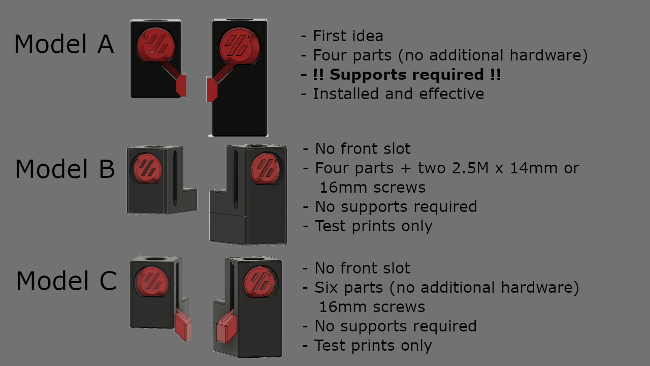
Model A - My initial idea. Added an arm to the Cam Lock. It requires supports, but worked well for me. Be aware, if the screws on the tophat are too tight, the cams will pull on that tab, but they do work well. Unique print orientation explained below.
Model B - No more flap! They also print in the stock V0 orientation. I just made a screw hole in the cam and a slot in the idler. So, it requires two 2.5mm x 14 mm or 16mm screws. My first version was a 3mm screw version. But this is a V0, we use 2.5mm screws here! (Let me know if you want the 3mm version.) Test model works great. This is definitely function over form. Bare screws aren't as pretty, but work great.
Model C - All the benefits of Model A and B. No flap, all printed parts, no additional hardware required. Camfers and Fillets should ensure fitment even if 1st layers is a little squished, but you definitely want to insert the arm and remove it a few times to ensure it is removable once installed. Printer tuning will determine best arms to use. I am using .1mm arms.
PRINT INSTRUCTIONS
Use standard voron print settings: 4 wall, 40% infill
Files should be in print orientation. That means…
B and C are default orientation. Cams on flat bottom with voron logo to front, Idlers standing with cam holes facing front.
For Model A, the idlers should be printed with the cutout side down, Cam hole forward. That ensures alignment and that the back wall holding the 1515 extrusion is properly solid. I used supports due to the recessed notch for the handle. Model B won't require them. (It is possible to print it upright, like the original. That makes the latch area smooth and clean, but if the tab isn't supported well, it can break off or be bent weirdly. I had a 50% success rate in that orientation. 100% in the orientation suggested.)
For Model A, the cams should be oriented with the Voron logo facing up. They need supports to ensure the proper shape of the cam lock.
INSTALLATION
Idlers install exactly like the originals.
For Models B and C, please insert the screws/arms into the idlers and remove them again before you put them in the idlers. It will ensure they are properly fit and removeable. The printed arms you may want to do a few times to ensure they are removeable if you need them to be.
IDLER INSTALL: Remove the tophat. Remove the side panels on lower frame. I remove the plexi mounts on the front side, then loosen the others and slide the panel out, toward the front. Remove the old locking cams, and the upper 1515 extrusions, with a single centered screw on each end. Now remove the original idlers, with the two screws through the upper idler down into the frame. I hold the lower idler and bearing stack while doing so, to try to keep everything together and aligned. Be sure you don't drop the washers above and below the bearings. Move the long screws to the new LazyCams Upper Idler, and slide them through the bearing stack and frame. Replace upper extrusion, ensuring alignment. Insert and tighten the screws centered in either side of the extrusion. Reinstall the side panel and tophat.
CAM LOCK INSTALL:
Model A - push the cam in from the front with the Voron logo facing the front, aligning the arm with the slot.
Model B - insert cam and hold it in place with your thumb. Align screw with the slanted channel on the bottom and screw it into the cam. Ensure slight clearance with the screw head and the idler.
Model C - I find these are more easily inserted with the cam rotated 45 degrees, to the open position. Once the arm is partially inserted, then rotate to the lower closed position and push up at a 45 degree angle until it is also flush with the idler.
You are done! No more tools to lock your tophat! And there there was much rejoicing.
If graphic instructions are needed, just ask.
DEVELOPMENT
The CAD files can be found here...
Voron0/LazyCams at main · akinferno/Voron0 (github.com)
Updated Github to include all the CAD files for A, B and C. Any problems, tips or suggestions would be appreciated. I want these to work for everyone :)