
Custom Threads for 3D Printing (Parametric)
We calculate the final price from your selected file. You review and accept it before payment.
Saved on this device.

Parametric, easy-to-print threads. Horizontal and vertical designs. Round and trapezoid threads.
- Rating
- 0 / 5
- Likes
- 19
- Downloads
- 209
- Makes
- 0
- Views
- 1,339
- Reviews
- 0
Updated at source:
Model information
- Source
- Printables
- Category
- Other Ideas
- License
- Creative Commons — Attribution — Noncommercial — Share Alike
It can be frustrating to reproduce threads found on household screws, nuts, and fasteners with 3D printing. The clearances are very small, the threads are sharp and thin, and the steep overhangs like to sag and collapse.
These threads were designed for FFF printers from the start. Since they are much easier to print, you should have lots of success.
No, they cannot replace traditional, metal fasteners. But with some creativity and clever engineering, they can help you simplify 3D printed projects.
Key Features
Thread size and shape that works with FFF limitations.
Clearances (tolerances) meant for 3D printing.
Printable overhangs.
Make a test print to find the perfect fit.
Horizontal and Vertical
The file for round threads generates parts that print in horizontal and vertical orientations. There are pros and cons to each one.
Horizontal | Vertical |
Relatively short print times for long screws. | Long print times for long screws. |
Layer stacking creates strong screws. | Layer stacking creates a weaker screw. |
Long and skinny screws are reasonably strong. | Thick and short screws are preferred over long and skinny ones. |
Thread size is limited by nozzle size. | Thread size is limited by layer height. |
Need to trim the bottom of screws and top of nuts for better printability. | No modifications or supports are required. |
Asymmetric parts. | Uniform, visually appealing parts. |
Screws are very sensitive to first layer squish. | Parts are not sensitive to first layer squish. |
Round threads only. | Round and trapezoid threads. |
Slicing and Printing
Bulging seams cause problems by adding friction and irregular bumps during rotation. Random seams spreads out the bumps, and scarf seams help minimize bumps on the cylindrical surfaces. Vertical parts experience the most problems with seams.
The horizontal screw is extra sensitive to elephant's foot and first layer squish. Due to the nature of parametric threads, I am not able to add a bottom chamfer. Therefore I highly recommend increasing elephant's foot compensation above your normal value.
Layer height is somewhat important. I got reasonable results with a layer height of 0.2 mm for all parts. When I reprinted parts with 0.1 mm layers, they were noticeably smoother. This is an expected outcome.
The round, horizontal nut makes very little contact with the print bed. I recommend adding a brim to it or trying the square nut instead.
You can add organic/tree supports to the roof of horizontal nuts. I added an extra gap here while creating the 3D model, so you may not need supports for small bridges. (I did not use supports for my test print.)
Parametric Design
Rather than deal with a myriad of sizes, I made a parametric design for Autodesk Fusion 360. This means that you assign values in the User Parameters window and the program will generate a new design. Within reason, it will make whatever size you want.
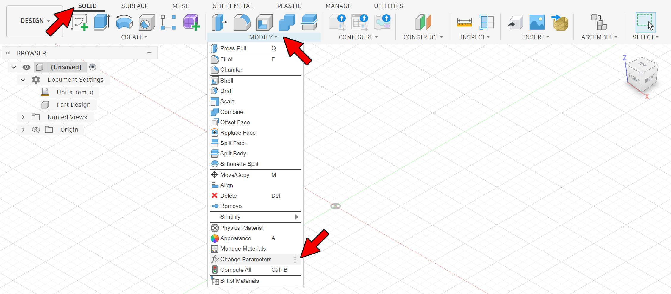
In the Solid workspace, click the Modify dropdown menu and select Change Parameters to bring up the User Parameters window.
TLDR Variables
You can simplify everything by using defaults and changing these five values.
Total clearance or tolerance. Change to match results from your test print. | tol_total |
Diameter of screw including threads | diameter_screw |
Threaded portion of screw. | length_threaded |
Length of the nut. | length_nut |
Screw head diameter. | head_diameter |
Variables
Feel free to edit these variables, but I do not promise that every combination will work. DO NOT edit calculated values.
Threads have a round (recommended) or trapezoid shape, illustrated below.

The parameters below control the basic shape of nuts and screws.
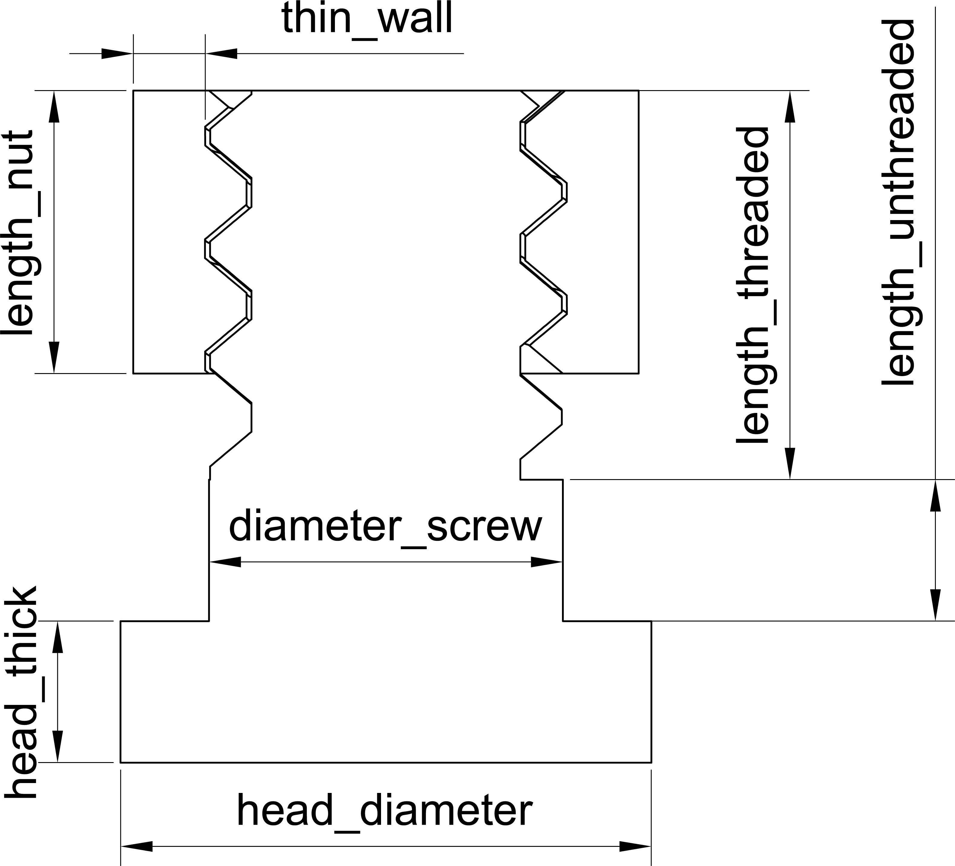
These parameters are used in every design.
Screw head diameter. Automatically adjusts if value is too small. | head_diameter |
Screw head thickness. | head_thick |
Diameter of screw. Minor diameter plus threads. | diameter_screw |
Size of threads. | thread |
Angled chamfer at the end of the screw, and both ends of the nut. | chamfer |
Overhang angle. Measured between print bed and part. | angle |
Total clearance/tolerance. | tol_total |
Clearance/tolerance for one side. Calculated value. | tol = tol_total/2 |
Threaded portion of screw. | length_threaded |
Length of nut. | length_nut |
Minimum wall thickness. Affects outer diameter of nut. | thin_wall |
And these variables only appear in specific designs.
Unthreaded portion of screw. | length_unthreaded |
Overhang angle for horizontal print orientation. Measured between printbed and part. | horizontal_trim_angle |
Additional Z clearance at the top of horizontal nuts. Allows bridge to sag without interfering with threads. | horizontal_trim_top |
Thickness of trapezoid threads. Prevents sharp edges for smooth motion. | trap_thick |
Sweep Errors
The program has trouble automatically updating the two sweep features in the timeline that create the threads. I am not sure what the exact problem is, but you can resolve the errors by clearing and reselecting the path and guiderail. It is a pretty quick fix.
Fixing the First Sweep
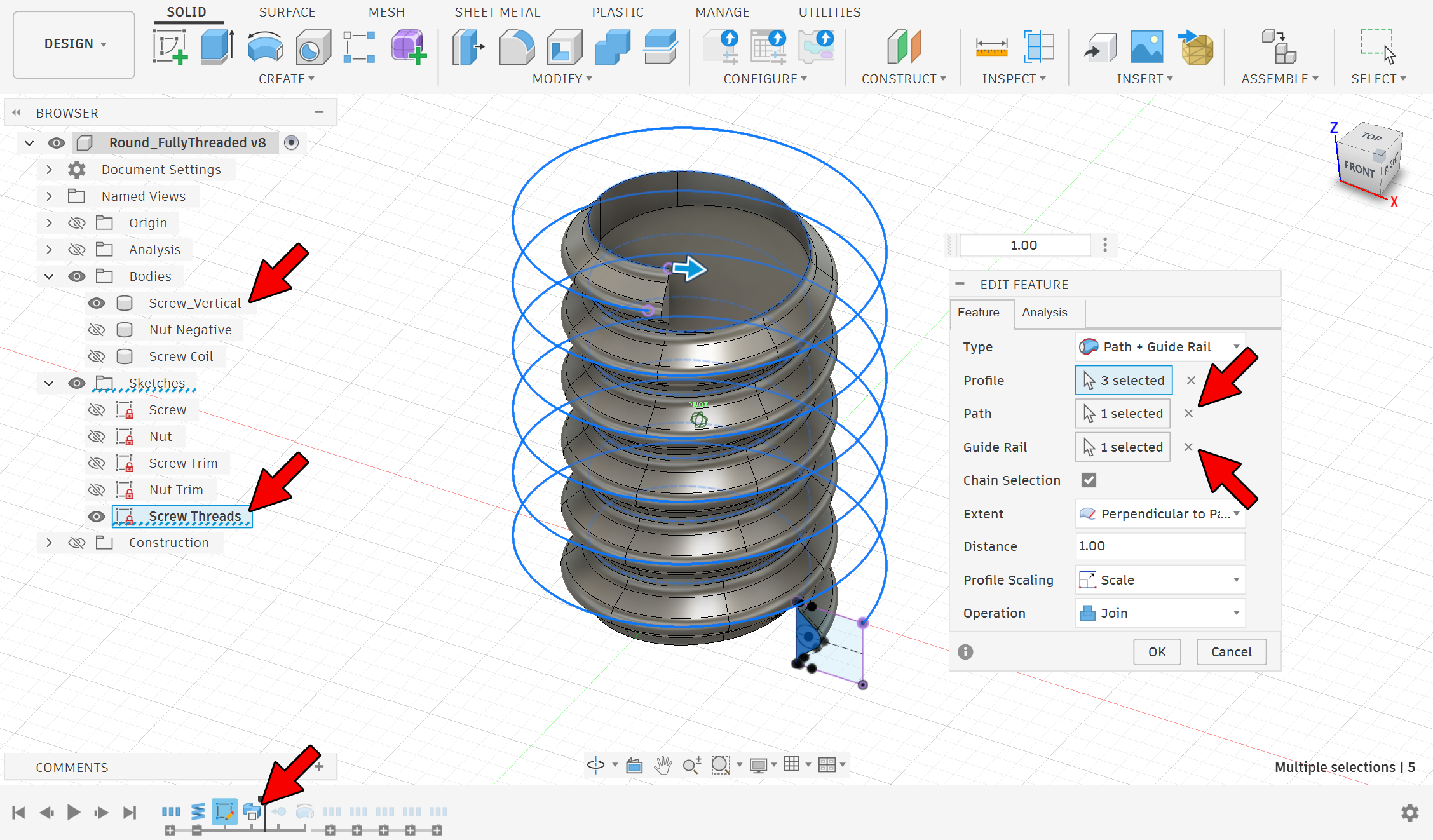
The first sweep creates threads for the screw. It is the third operation in the second group.
Double click on the feature in the timeline (bottom left).
Visible items in the design tree (top left) will have a filled-in, dark grey eye.
Double check that Screw_Vertical is the only visible body.
Double check that Screw Threads is the only visible sketch.
Click the X next the Path and Guiderail in the popup to clear the previous selections.
Click the Path button and select the dotted line that spirals up.
Click the Guiderail button and select the solid line that spirals up.
If everything worked, the operation is Join and the OK button is enabled. (The program can pause or stutter for long threads.)
Click the OK button.
The body Screw_Vertical should now have threads.
Fixing the Second Sweep
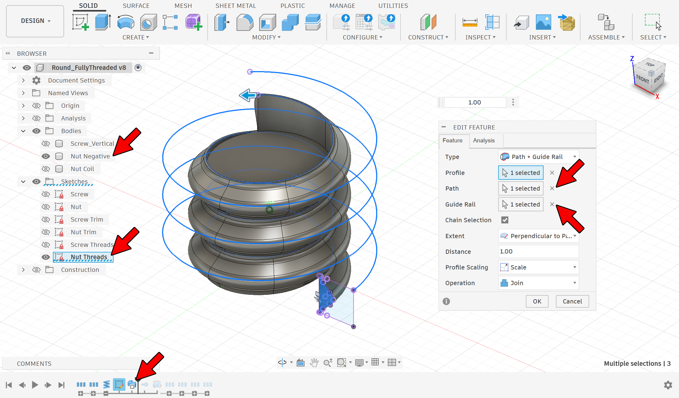
The second sweep creates threads for the nut. It is the third operation in the third group.
Double click on the feature in the timeline (bottom left).
Visible items in the design tree (top left) will have a filled-in, dark grey eye.
Double check that Nut_Negative is the only visible body.
Double check that Nut Threads is the only visible sketch.
Click the X next the Path and Guiderail in the popup to clear the previous selections.
Click the Path button and select the dotted line that spirals up.
Click the Guiderail button and select the solid line that spirals up.
If everything worked, the operation is Join and the OK button is enabled. (The program can pause or stutter for long threads.)
Click the OK button.
The body Nut_Negative should now have threads.
Revision 2
All of the previous files are available in archive.zip. The original design has become less stable over time as Fusion updates. I have tried to make the new design update with as few errors as possible.
I added a test print. It will help you dial in settings, and gives everyone a sample print without having to use Fusion. I reorganized sketches so that they should be easier to follow and understand. I also corrected the mathematical formula that calculates the profile for round threads. (Props if anyone even noticed it.) And finally, I added square nuts and horizontal nuts to the design file.
Thanks for visiting, and enjoy!