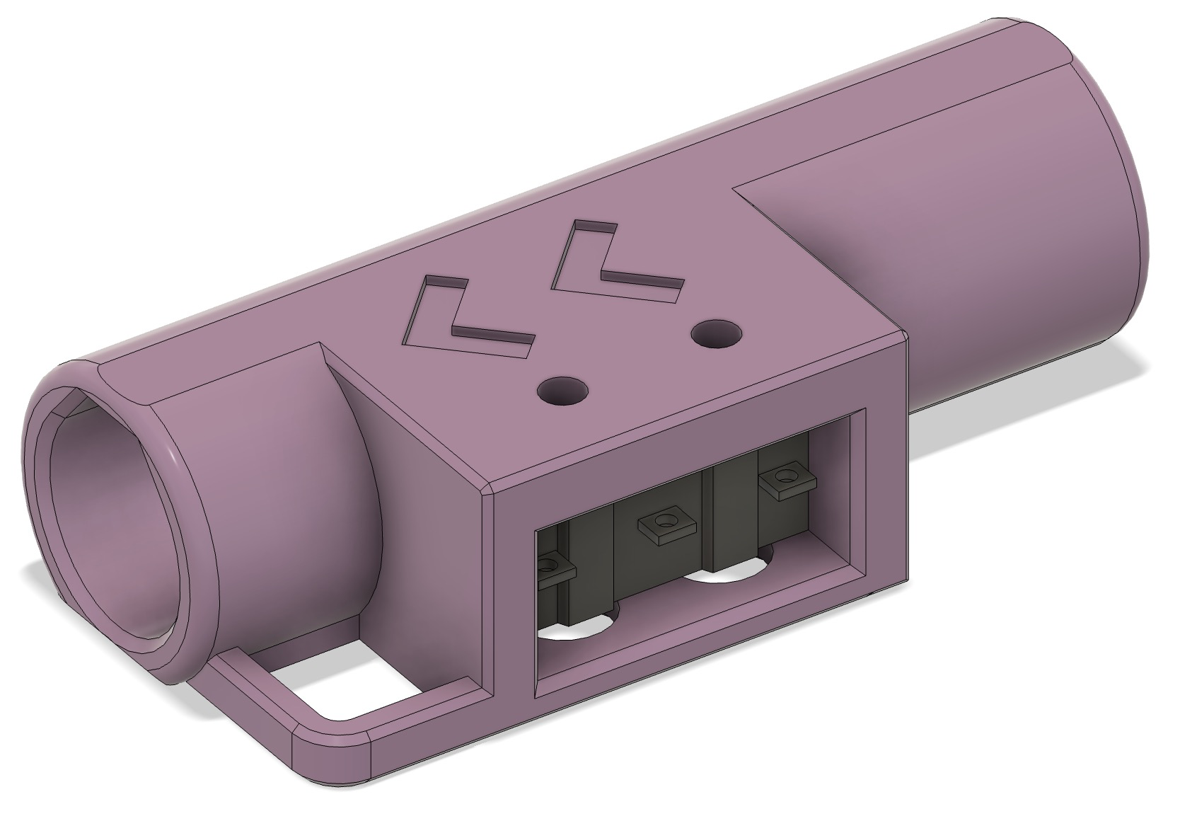
Standalone Filament Sensor & Happy Hare / ERCF / Tradrack pre-gate sensor using lever switches
Obliczymy ostateczną cenę na podstawie wybranego pliku. Sprawdzisz ją i zaakceptujesz przed płatnością.
Zapisane na tym urządzeniu.

A standalone filament pre-gate sensor that uses lever switches for improved reliability and reduced friction.
- Ocena
- 5 / 5
- Polubienia
- 68
- Pobrania
- 307
- Wydruki
- 2
- Wyświetlenia
- 2838
- Oceny
- 2
Aktualizacja u źródła:
Informacje o modelu
- Źródło
- Printables
- Kategoria
- Voron Parts & Upgrades
- Licencja
- Creative Commons — Attribution — Share Alike
A standalone filament pre-gate sensor that uses lever switches instead of the more typical ball bearings and switch approach.
This sensor can be used both for the ERCF/Tradrack MMUs using Happy Hare, as well as a standalone filament runout sensor. By using the Omron D2F-L3-D3 switches, the effective actuation range of the switch is increased. This results in reduced false positives caused by filament diameter variation, filament grinding in the ERCF/Extruder gears, and also reduces wear on the switch itself as the contact is stationary.
Design Inspiration
This design was inspired by and heavily drawing on the CAD work done by Juliusjj25 to implement filament sensors embedded in the ERCF gates. This design has been modified to operate stand alone, the filament path has been optimised for reduced friction and improved reliability with the endless spool in Happy Hare. Additionally, the design has been amended to allow for printing without supports.
Benefits of Using with Happy Hare and ERCF/Tradrack
- Improved Endless Spool Reliability: The sensor is designed to be placed at a distance from the MMU gates. This helps improve endless spool reliability by reducing the likelihood that the filament travels past the MMU gate before Klipper pauses the print.
- Optimized Filament Path: The carefully designed filament path allows for low friction and low "collision" retraction from the MMU back to your buffer of choice. This reduces the probability of filament stalling and getting stuck before reaching the buffer.
- Improved integration with the Filamentalist buffer, allowing for more reliable endless spool and flexible placement of the sensor and filamentalist.
Print Settings
- Layer Height: 0.16-0.2mm layer height (0.16mm recommended), with a 0.25mm first layer height.
- Walls: 4 walls, with a 0.4mm forced extrusion width.
- Wall Generation: Use classic wall generator with thin wall detection enabled.
- Wall Odering: Inner - Outer only. Outer-inner (External perimeter first) and Inner-Outer-Inner will not provide the level of overhang quality needed to print the model with the right tolerances. If using Orca slicer, enable the Precise Wall option for better surface finish.
- Bridges: Ensure thick bridges are disabled in your slicer.
- Infill: 40%, gyroid.
- Top and Bottom surfaces: 5 (when using 0.16 LH), or 4 (when using 0.2 LH)
- Print in ABS or ASA - model has been designed to account for material shrinkage, so please disable shrinkage compensation in the slicer.
- Make sure your filament flow rate is calibrated correctly. The part requires a well calibrated printer to deliver the required tolerances for reliable operation. If in doubt, prit the ERCF / Voron calibration tests.
BOM
Per sensor:
| Item | Quantity | Sourcing |
|---|---|---|
| Omron D2F-L3-D3 switch | 1 per sensor | Digikey / Mouser / Farnell |
| M2x8 or 10mm Self-Tapping screws | 2 per sensor | Amazon, Aliexpress, included in the ERCF kit |
| Ziptie | 1 per sensor | Amazon, Aliexpress |
| 22AWG silicone cable | As needed | Amazon, Aliexpress, included in the ERCF kit |
| Heatshrink tubing (optional) | As needed | Amazon, Aliexpress, Hardware stores |
| Soldering iron & solder | As needed | Amazon, Aliexpress, Hardware stores |
| ECAS fittings | 2 per sensor | Amazon, Aliexpress, Hardware stores |
Assembly tips
- Make sure your bridges have printed cleanly, so the switch slides in the housing without any force. If your bridges are not "clean" you may end up depressing the level switch at installation!
- Position the switch and set the two screws. Dont screw them in fully as you may need to slightly adjust the switch position below.
- Taking turns, screw one screw a bit at a time till both are tight. If the switch clicks, back the screw out a bit and reposition the switch slightly so it is secure without it being activated!
- Place the ecas fittings and solder the wires to the switches as per your MMU's instructions.
- Run a fragment of filament through by hand to clear out and loosen thr filament path.
- Print without supports. Holes are supported internally.
IMPORTANT: The sensor is directional! The arrows must point to the filament path direction - i.e. pointing towards your MMU/printer. While the sensor can be installed in reverse, its performance will be sub optimal as the filament path drag has been optimised to enable smooth filament re-wind when performing endless spool operations.
If you're using this as a stand alone filament sensor install it flipped so the arrows point to your filament spool and not the printer. This will make filament loading easier since automated endlews spool operation is not needed in that case.
IMPORTANT: When loading your MMU make sure the end of the filament is straight - this will help the filament ease through the sensor without it catching.
Images: