
Elecraft KH1 Mini Screwdriver Loading Coil
Obliczymy ostateczną cenę na podstawie wybranego pliku. Sprawdzisz ją i zaakceptujesz przed płatnością.
Zapisane na tym urządzeniu.
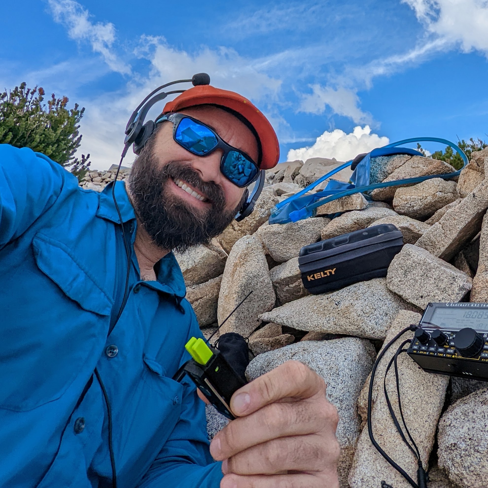
Enable your KH1 to tune all bands with no counterpoise using just the whip and this loading coil.
- Ocena
- 5 / 5
- Polubienia
- 46
- Pobrania
- 294
- Wydruki
- 5
- Wyświetlenia
- 3276
- Oceny
- 4
Aktualizacja u źródła:
Informacje o modelu
- Źródło
- Printables
- Kategoria
- Portable Devices
- Licencja
- Creative Commons — Attribution — Noncommercial — Share Alike
BACKGROUND:
The Elecraft KH1 blew up the portable HF radio operating scene when it was released. It covers 5 bands from 40 - 15 m and has an internal ATU and battery. It's actually designed for hand-held use.
But with the standard whip antenna, there isn't enough inductance to reach below 20 m. Elecraft designed some loading coils, but they're relatively big and more costly (and arguably more efficient). I wanted something small, that I could mount on the radio, and without unscrewing anything, tune to all bands.
BILL OF MATERIALS:
Links are Amazon Affiliate links - It costs you nothing more, but I get a few cents on the dollar from Amazon if you purchase through these links.
| Mandatory Items | Qty | Source |
| 3d Printed Shell | 1 | Print it using the attached STL |
| 3d Printed Plug | 1 | Print it using the attached STL |
| 3d Printed Ring | 1 | Print it using the attached STL |
| M4 x 10mm heat-set insert | 1 | https://amzn.to/4a9K4Ec |
| 26 ga magnet wire | 1 | https://amzn.to/3DIzVSH |
| 26 ga insulated wire (preferably Poly Stealth) | 4 in | www.davisrf.com/antenna-wire/polystealth.php Alternate: https://amzn.to/3C2uhKv |
| M4x12mm Stainless Steel Screw | 1 | https://amzn.to/4fMvLq6 |
| M4 Stainless Steel Nut | 1 | https://amzn.to/4iXHyVx |
| CA glue (aka “Super Glue”) | 1 | https://amzn.to/3PpBNlG |
| Sandpaper (180 - 400 grit will do) | 1 | https://amzn.to/49Zpd6p |
| PETG Filament | ~5 g | https://amzn.to/3H9QN4p |
TOOLS:
- 3d Printer capable of printing PETG
- 2.5 mm hex driver ( https://amzn.to/4gVHV0X )
- Tweezers ( https://amzn.to/3BaOeex )
- Soldering iron ( https://amzn.to/3PmnUVK )
ASSEMBLY:
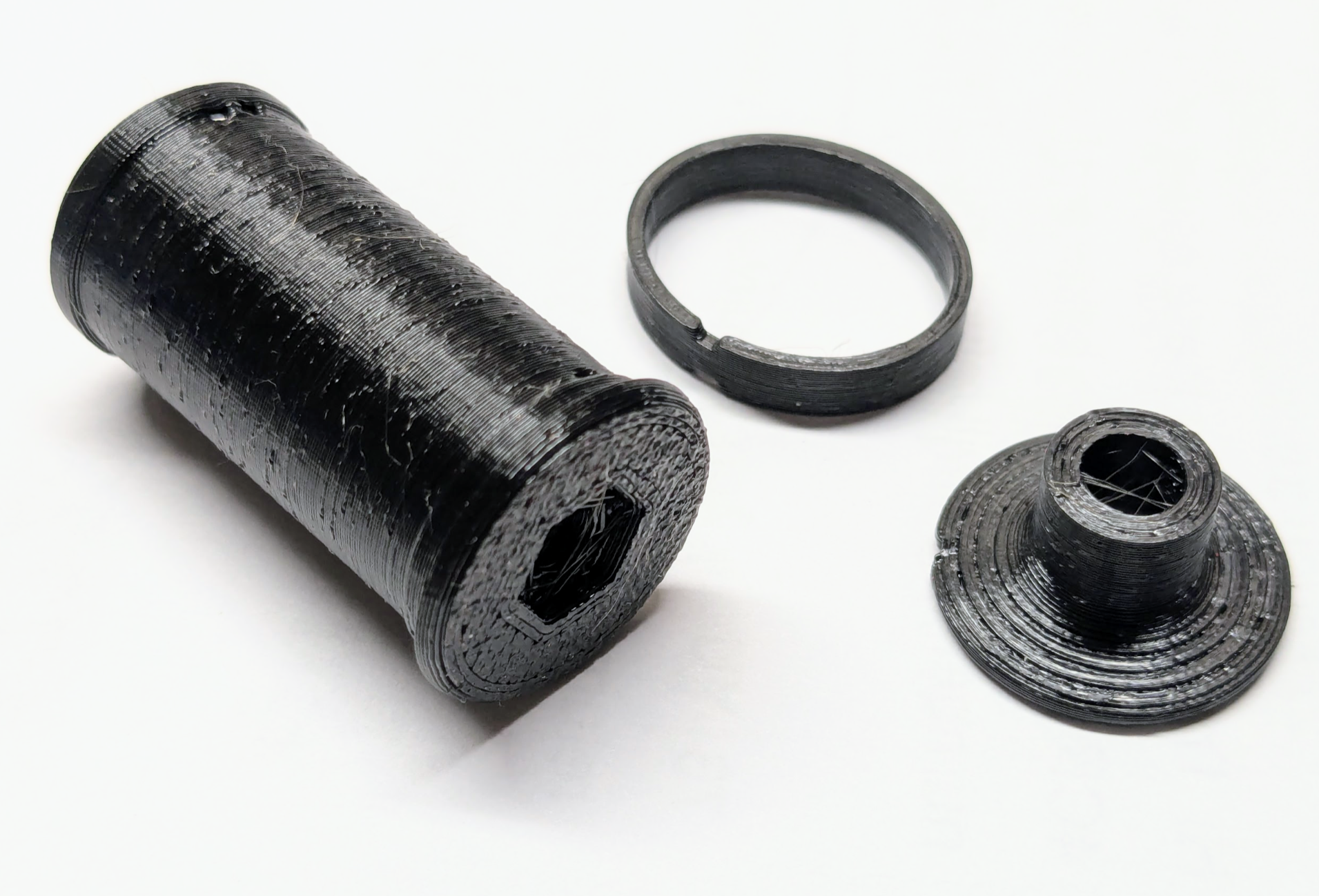
1.) Print all the things.
I've included the GCode I use on a Prusa i3 Mk ii if you want to just download and hit “print.”
Orient the parts with the largest solid side down for best printing.
Supports should not be necessary for any of the prints, and if you dry your filament, your prints should look better than mine.
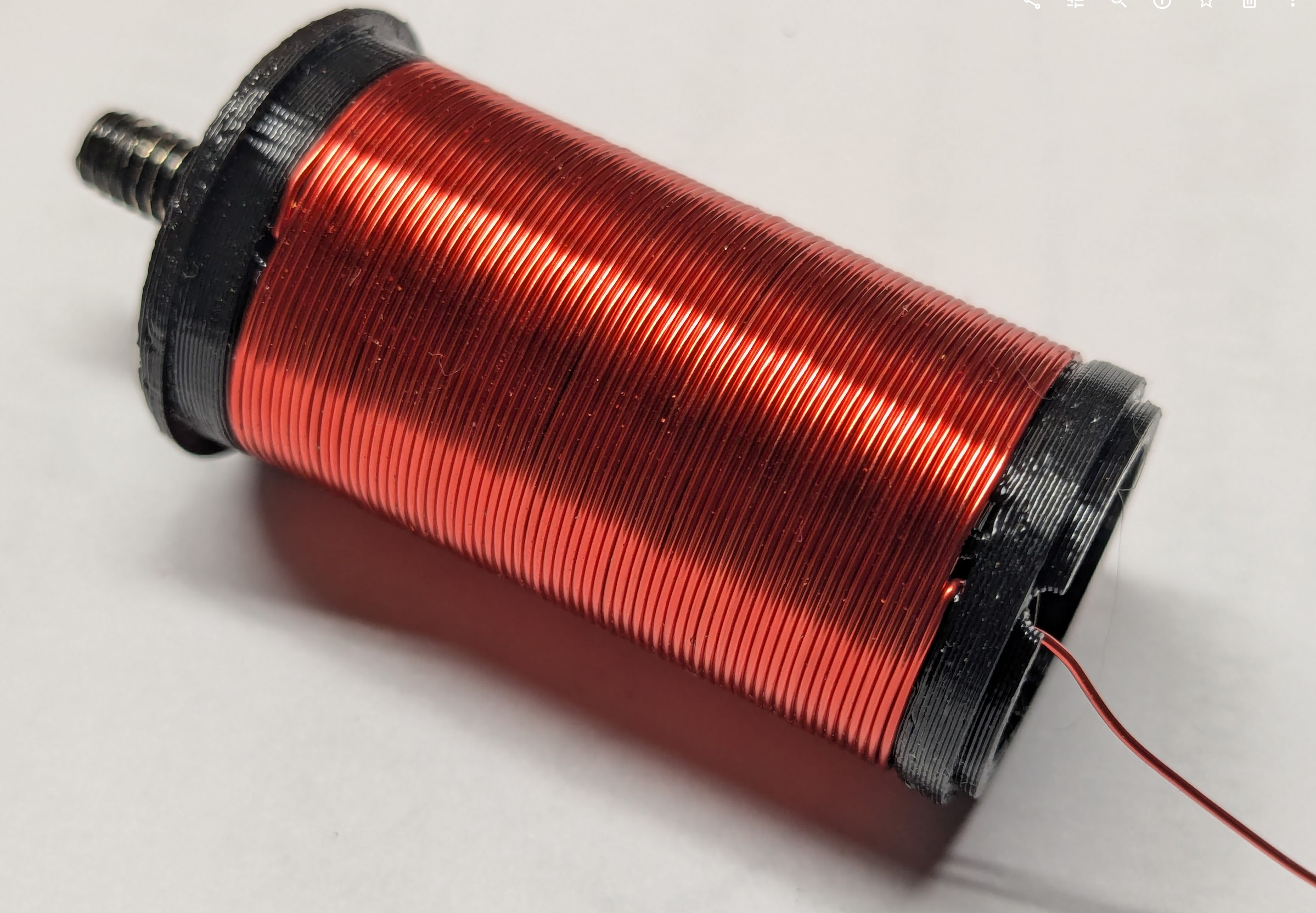
2.) Strip the end of the magnet wire and secure it in the screw hole.
Scrape the enamel off of about ½" of the end of the magnet wire.
Stick the wire into the side hole at the hexagonal end of the coil form and out through the screw hole.

Insert the screw from the bottom and press it into the hole. Secure the screw with a nut, tightening it all the way. The magnet wire should be held firmly in place.

3.) Wind the coil.
Wind the coil under tension, minimizing gaps by periodically compressing the wire together.
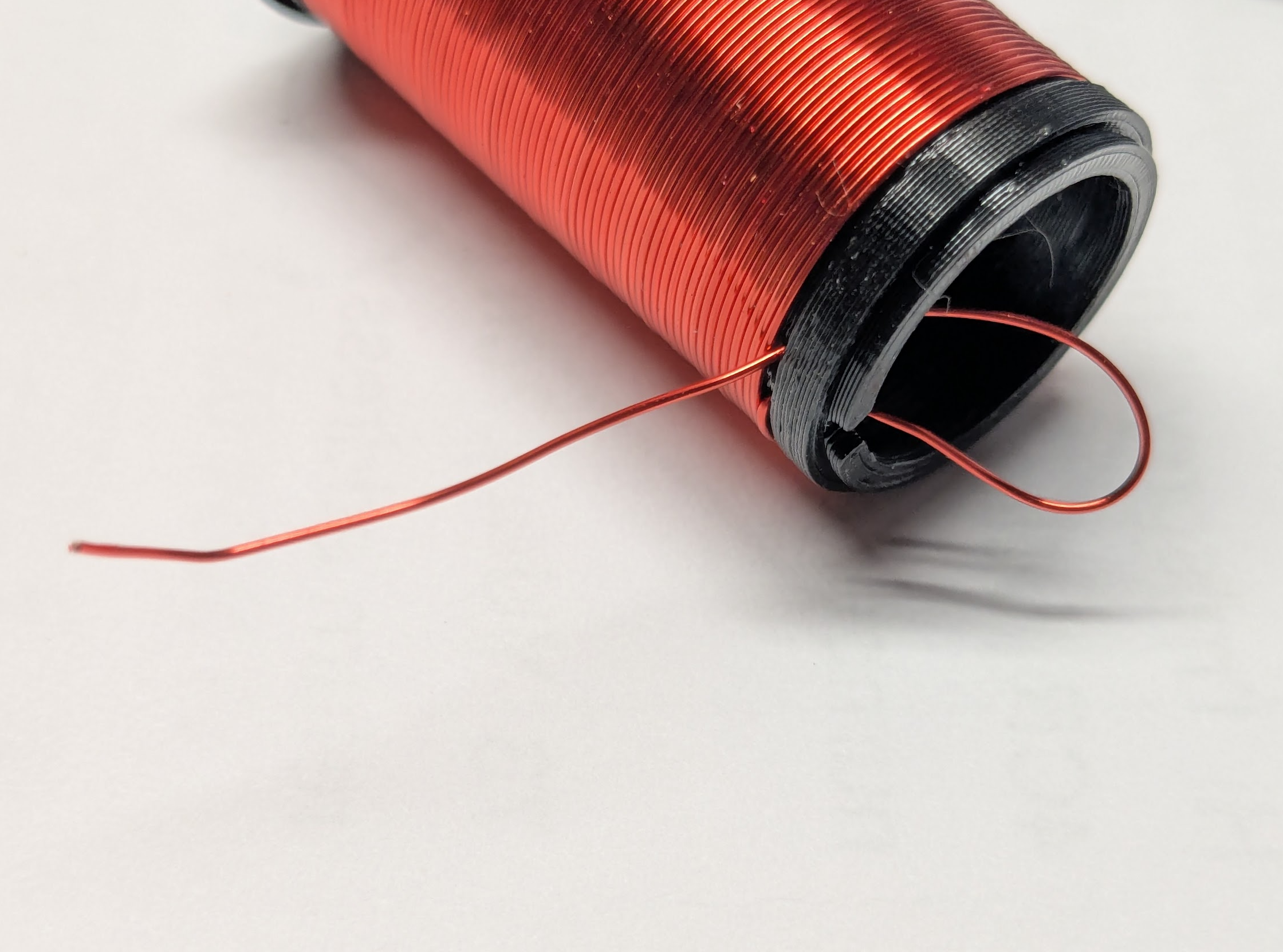
When you reach the end of the coil form with the two holes, cut the magnet wire with about 6" extra.
Stick the wire through the first hole, then back out of the second hole, then back into the first hole to secure the wire in place.


4.) Press the insert into the plug.
Take the plug piece and heat-set insert and press the insert into place using a soldering iron.
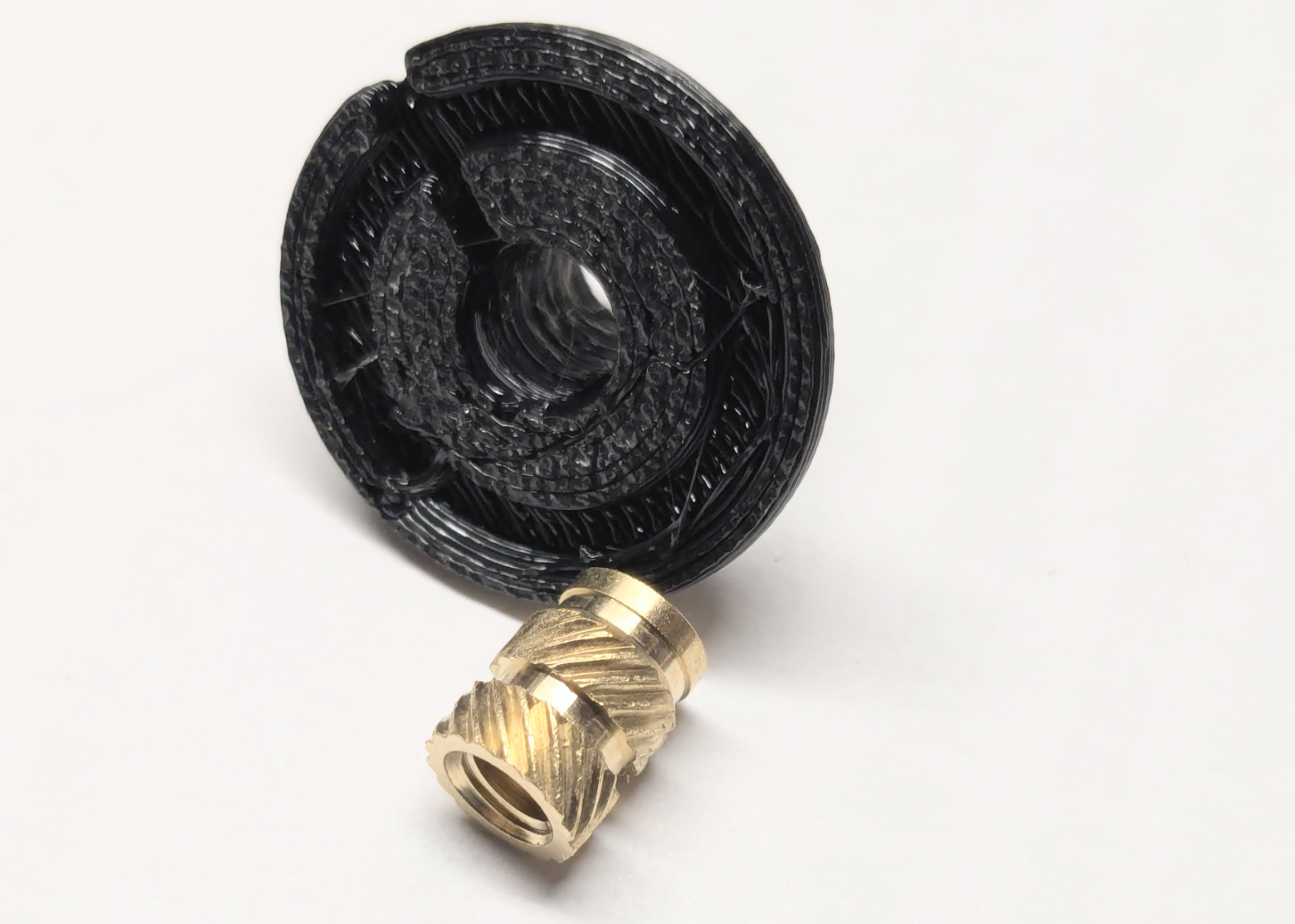

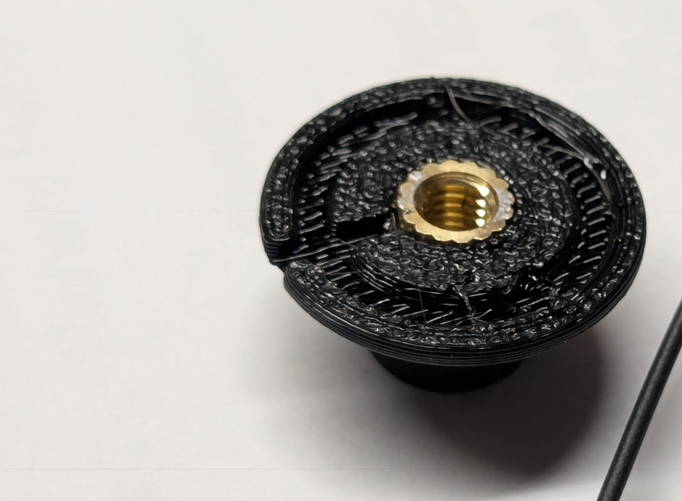
If necessary, clean up any accumulated plastic from the skinny end of the plug using tweezers.
5.) Attach the wire to the ring.
Strip about ¾" of insulation from one end of a piece of wire. Split the strands into two even bundles and twist each bundle.
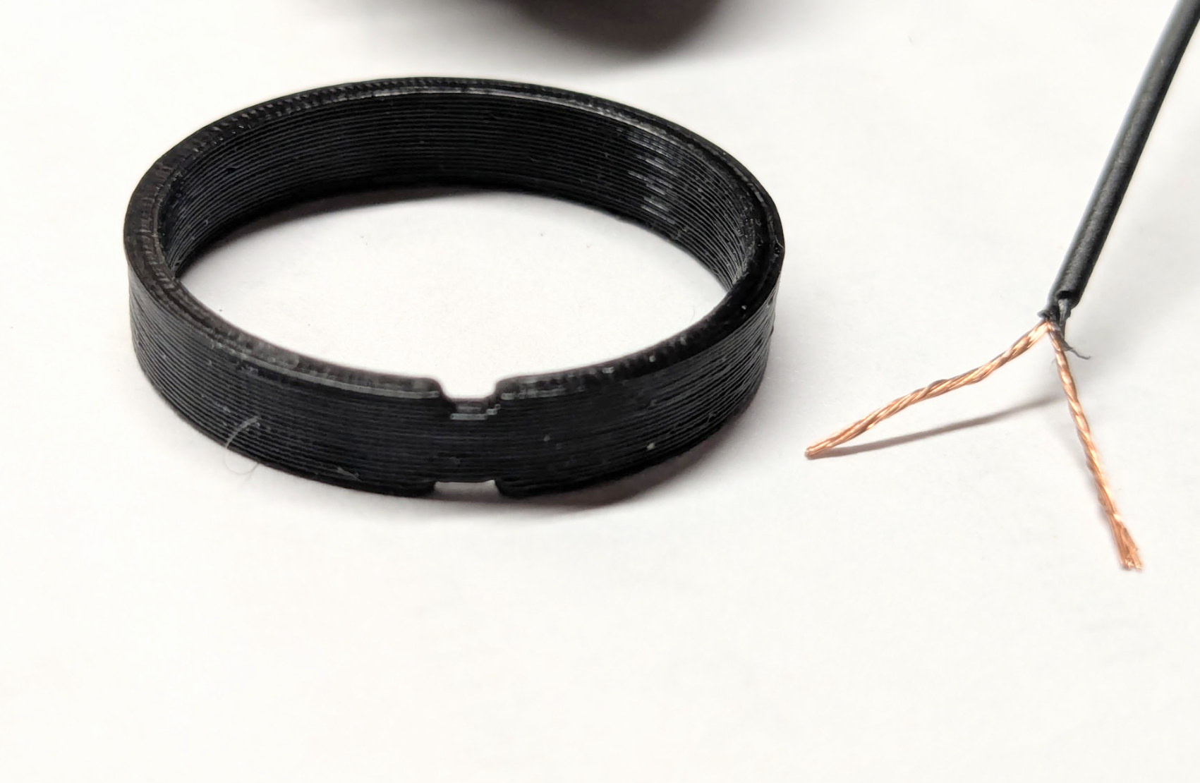
Wrap the wire bundles around the notch in the ring as tightly as possible. Tweezers help.

Trim the wire, end, fold it over, and solder QUICKLY to prevent melting through the ring. It may help to place the ring onto the coil while soldering to act as a heat sink and hold it in place.
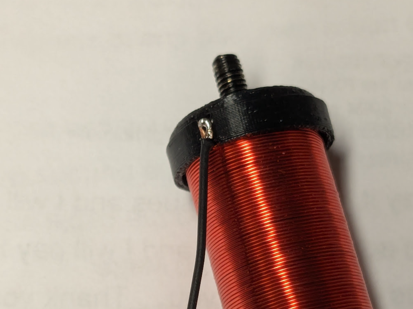
6.) Sand the coil.
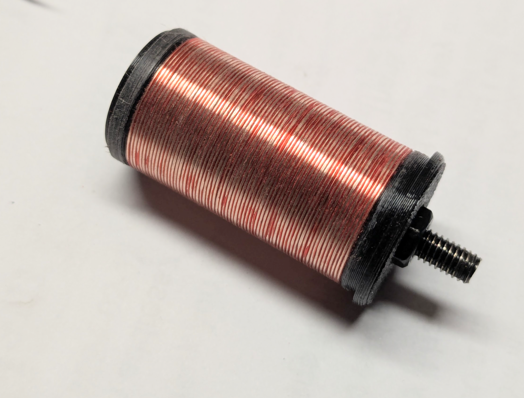
Use sandpaper to remove the enamel from the outside of the coil wires.
I like to carefully place the threaded screw in the chuck of a screwdriver (without damaging the threads!) and use that to slowly spin the coil while sanding.

Remove enough enamel to allow the wire on the ring to make contact with the coil.
7.) Trim and solder wire to plug.
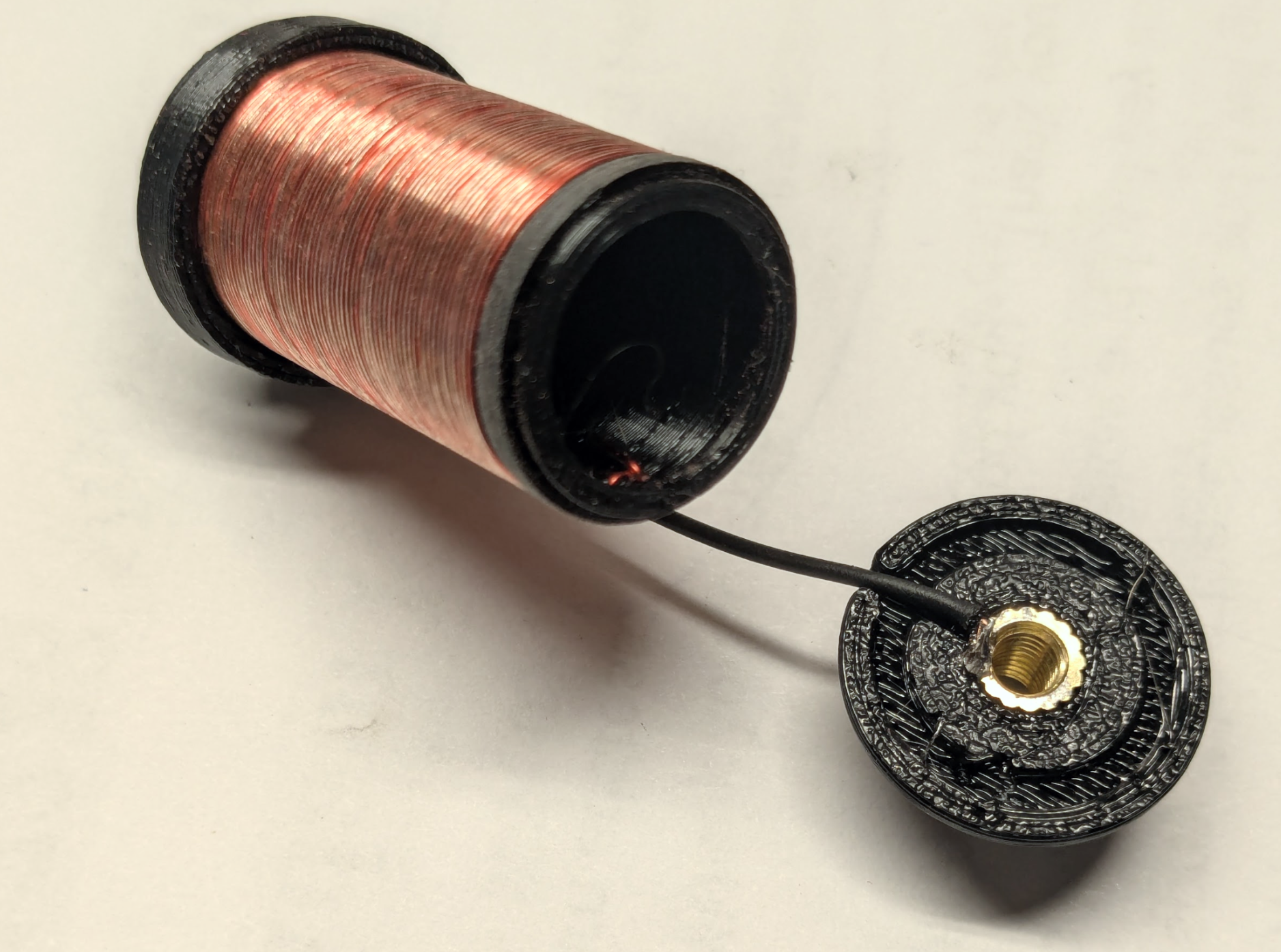
Place the ring on the coil and slide it to the screw end of the coil. Trim the insulated wire about ¾" longer than the coil. Strip about 1/8" of insulation from the end and solder the end to the rim of the heat-set insert in the plug so the wire sits in the groove on the plug.
8.) Glue the plug to the coil.
Apply a liberal amount of super glue to the base ring of the coil or the round groove on the plug. Align the wire into the groove on the plug and the notch on the coil and press the two pieces firmly together.
CAUTION: Allow to cure for at least an hour before testing. This glued joint must endure a significant amount of stress in use. For a firm bond, I prefer to clamp the unit under light pressure while curing.
9.) Operate with it!
Attach the whip to the screw, and attach the base to the KH1. Adjust the ring listening for the strongest received noise level.
To adjust the tap, squeeze the sides of the elliptical ring to compress it slightly and allow it to slide easier.
With the ring near the top of the coil and the KH1 whip switch in the 17 m position, it should tune well on 15 m and 17 m with just the capacitance of your hand holding the radio.
With ring just below the top, and the switch in the 20 m position, it should tune 20 m well.
With the ring just below half-way, and the switch in the 20 m position, it should tune 30 m.
And with the ring near the base of the coil, and the switch in the 20 m position, it should tune 40 m.
Adding a counterpoise will likely help with efficiency, but with this coil, you can operate without one. I have made contacts even on 40 m with this setup, without a counterpoise, so although it's inefficient, it is possible.
Thanks for building!
Please like this page and share your build with comments, particularly if you have anything you would improve about this design.